Method for making an acoustic panel for the air intake lip of a nacelle

a technology of air intake and nacelle, which is applied in the direction of instruments, air transportation, jet propulsion plants, etc., can solve the problems of affecting the airflow direction, affecting the aerodynamic properties of the air intake, and generating significant noise pollution for the turboshaft engines of aircraft, so as to achieve effective de-icing and simple production

Inactive Publication Date: 2013-11-19
SAFRAN NACELLES
View PDF13 Cites 5 Cited by
  • Summary
  • Abstract
  • Description
  • Claims
  • Application Information

AI Technical Summary

Benefits of technology

[0013]One aim of the present invention is therefore to provide an air intake lip comprising an acoustic treatment and effective de-icing while also being simple to make.

Problems solved by technology

The presence of ice or frost modifies the aerodynamic properties of the air intake and disturbs the conveyance of the air towards the fan.
Moreover, aircraft turboshaft engines generate significant noise pollution.
However, it is necessary to make the acoustic treatment compatible with the de-icing method using an electric resistance, which is difficult to achieve.

Method used


Image

  • Method for making an acoustic panel for the air intake lip of a nacelle
  • Method for making an acoustic panel for the air intake lip of a nacelle
  • Method for making an acoustic panel for the air intake lip of a nacelle

Examples


Embodiment Construction

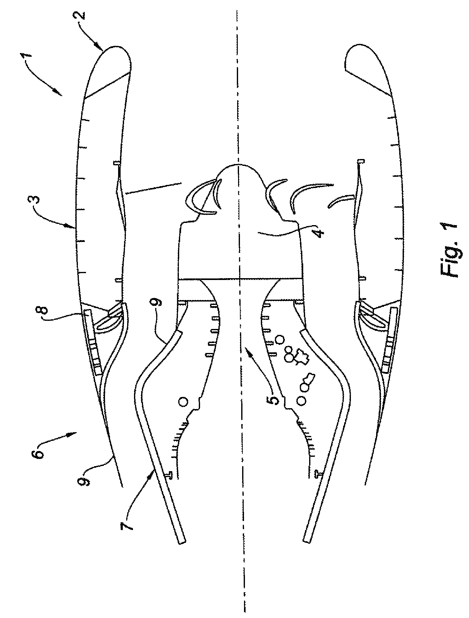
[0046]As shown in FIG. 1 for a turbojet engine, a nacelle 1 according to the invention comprises an air intake lip 2, a middle structure 3 surrounding a fan 4 of the turboshaft engine 5 and a downstream assembly 6. The downstream assembly 6 is formed by an inner fixed structure 7 (IFS) surrounding the upstream portion of the turboshaft engine 5, an outer fixed structure 8 (OFS), and a mobile cowling 9 comprising a thrust reverser means.

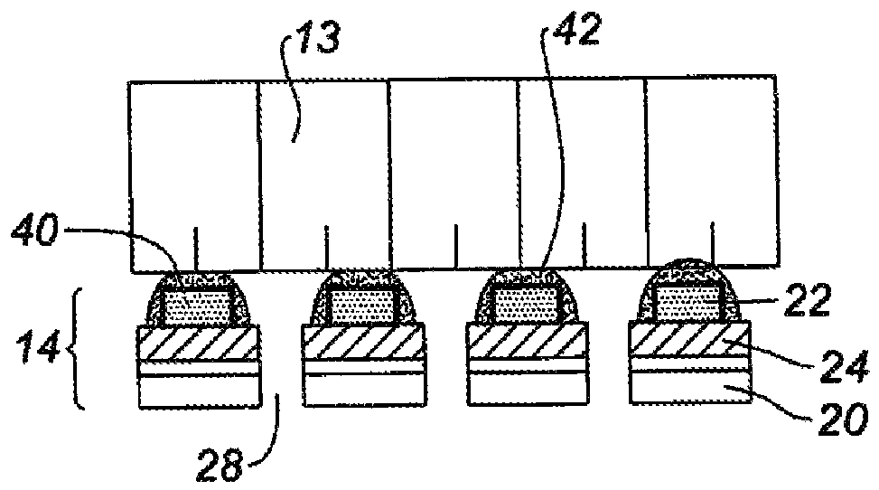
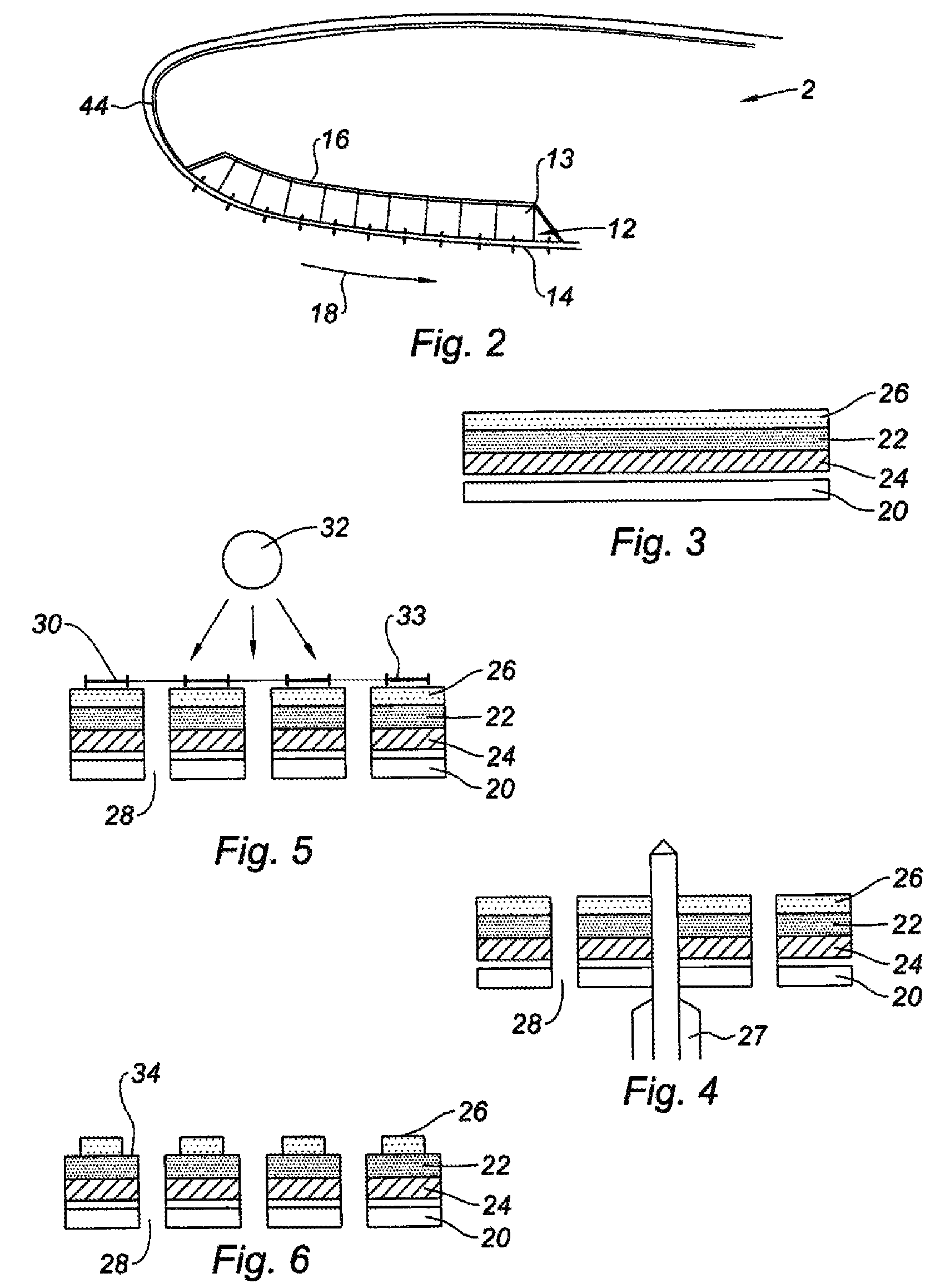
[0047]As shown in FIG. 2, the air intake lip 2 according to the invention comprises, in certain zones, an acoustic panel 12 in order to absorb the sound pollution due to the operation of the turboshaft engine 5. The acoustic panel 12 includes a honeycomb structure 13 on which a perforated de-icing assembly 14 is attached and a solid inner skin 16. The de-icing assembly 14 is in contact with the cold air flow 18, which is not the case with the inner skin 16.

[0048]The acoustic panel 12 is obtained using the method according to the invention comprising t...


PUM

PropertyMeasurementUnit
diameteraaaaaaaaaa
diameteraaaaaaaaaa
diameteraaaaaaaaaa

Abstract

The invention relates to a method for making an acoustic panel (12) for an air intake lip (2) of a nacelle (1) that includes the steps of obtaining a perforated de-icing assembly (14) including at least one array of conducting members obtained by a photolithographic method, said de-icing member (14) being secured to a structure with a cellular web (13). The invention also relates to an air intake lip and to a nacelle.

Description

TECHNICAL FIELD[0001]The invention relates to a method for making an acoustic panel with an air intake lip including a de-icing assembly.[0002]The invention also relates to a nacelle for a turboshaft engine comprising such an air intake lip.BACKGROUND[0003]An airplane is propelled by one or several propulsive assemblies each comprising a turboshaft engine housed in a substantially tubular nacelle. Each propulsive assembly is attached to an aircraft by a mast situated under a wing or at the fuselage.[0004]A nacelle generally has a structure comprising an air intake upstream of the engine and a middle section able to surround a fan of the turboshaft engine, a downstream section generally housing thrust reverser means and able to surround the combustion chamber of the turboshaft engine. The nacelle typically ends with an ejection nozzle, the outlet of which is situated downstream of the turboshaft engine.[0005]The air intake comprises, on one hand, an intake lip adapted to allow optima...

Claims


Application Information

Patent Timeline
Patent Type & Authority Patents(United States)
IPC IPC(8): B21D53/92B64C23/00B64D15/12
CPCB64D33/02F02C7/045F02C7/047H05B3/267H05B3/286B64D2033/0233Y02T50/672Y02T50/60Y10T29/4932Y10T29/49622
Inventor CARUEL, PIERRE
Owner SAFRAN NACELLES
Why Eureka
Try Eureka