Hand-held power tool

a power tool and hand-held technology, applied in the field of hand-held power tools, can solve the problems of slight tilting of the intermediate striker and decrease in length, and achieve the effect of facilitating closur

Active Publication Date: 2018-08-28
HILTI AG
View PDF28 Cites 4 Cited by
  • Summary
  • Abstract
  • Description
  • Claims
  • Application Information

AI Technical Summary

Benefits of technology

[0003]It is an object of the present invention to provide a hand-held power tool having a tool socket, a motor and a pneumatic striking mechanism. The striking mechanism has an exciter driven by the motor along a working axis, a striker coupled to the exciter via an air cushion, and an intermediate striker arranged between the striker and the tool socket in the striking direction. The striking mechanism also has a guide in which the intermediate striker is guided. The guide has a first sliding surface that guides a first section of the intermediate striker, and a second sliding surface that is arranged offset relative to the first sliding surface in the striking direction and that guides a second section of the intermediate striker. A radial dimension of the first section of the intermediate striker is greater than a radial dimension of the second section of the intermediate striker. The intermediate striker is preferably guided on its section that is closest to the tool and on its section configured with the largest diameter. The guide length of the intermediate striker during operation is large since then, the intermediate striker is retracted into the guide essentially opposite to the striking direction. When an empty strike occurs, the intermediate striker typically slides in the striking direction until it reaches a stop. The guide length decreases in this process, which can give rise to a slight tilting of the intermediate striker. This slight tilting facilitates the switching off of the striking mechanism after an empty strike.
[0009]In one embodiment, a sealing ring is arranged on the second sliding surface. The second sliding surface and the second section of the intermediate striker are preferably sealed with each other so as to be air-tight and dust-tight. The sealing ring can facilitate the closure.

Problems solved by technology

The guide length decreases in this process, which can give rise to a slight tilting of the intermediate striker.

Method used


Image

  • Hand-held power tool
  • Hand-held power tool
  • Hand-held power tool

Examples


Embodiment Construction

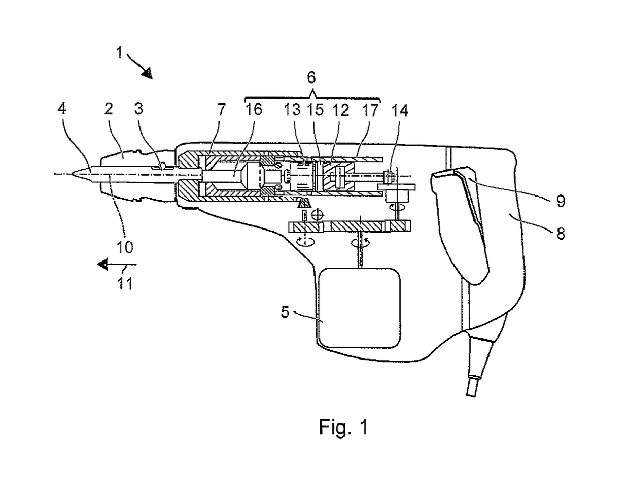
[0016]FIG. 1 schematically shows a hammer drill 1 as an example of a chiseling hand-held power tool. The hammer drill 1 has a tool socket 2 into which a shank end 3 of a tool, e.g. a drill chisel 4, can be inserted. A motor 5 that drives a striking mechanism 6 and a drive shaft 7 constitute the primary drive of the hammer drill 1. A user can hold the hammer drill 1 by means of a handle 8 and can start up the hammer drill 1 by means of a system switch 9. During operation, the hammer drill 1 continuously rotates the drill chisel 4 around a working axis 10, and in this process, it can hammer the drill chisel 4 into a substrate in the striking direction 11 along the working axis 10.

[0017]The striking mechanism 6 is, for example, a pneumatic striking mechanism 6. An exciter 12 and a striker 13 are installed in the striking mechanism 6 so as to be movable along the working axis 10. The exciter 12 is coupled to the motor 5 via an eccentric 14 or a toggle element, and it is forced to execut...


PUM


Abstract

The hand-held power tool has a tool socket, a motor and a pneumatic striking mechanism. The striking mechanism has an exciter driven by the motor along a working axis, a striker coupled to the exciter via an air cushion, and an intermediate striker arranged between the striker and the tool socket in the striking direction. The striking mechanism also has a guide in which the intermediate striker is guided. The guide has a first sliding surface that guides a first section of the intermediate striker, and a second sliding surface that is arranged offset relative to the first sliding surface in the striking direction and that guides a second section of the intermediate striker. A radial dimension of the first section of the intermediate striker is greater than a radial dimension of the second section of the intermediate striker.

Description

[0001]This claims the benefit of German Patent Application DE 102012212231, filed Jul. 12, 2012 and hereby incorporated by reference herein.[0002]The present invention relates to a chiseling or drilling-chiseling hand-held power tool.SUMMARY OF THE INVENTION[0003]It is an object of the present invention to provide a hand-held power tool having a tool socket, a motor and a pneumatic striking mechanism. The striking mechanism has an exciter driven by the motor along a working axis, a striker coupled to the exciter via an air cushion, and an intermediate striker arranged between the striker and the tool socket in the striking direction. The striking mechanism also has a guide in which the intermediate striker is guided. The guide has a first sliding surface that guides a first section of the intermediate striker, and a second sliding surface that is arranged offset relative to the first sliding surface in the striking direction and that guides a second section of the intermediate strik...

Claims


Application Information

Patent Timeline
Patent Type & Authority Patents(United States)
IPC IPC(8): B25D11/06B25D17/06
CPCB25D11/06B25D17/06B25D2211/003B25D2211/068B25D2250/345B25D2217/0019B25D2250/225B25D2250/231B25D2217/0015
Inventor WIEDNER, AARONHARTMANN, MARKUS
Owner HILTI AG
Why Eureka
Try Eureka