Safety device for orienting a motor-vehicle front wheel transversally to the longitudinal direction following a collision

a safety device and motor vehicle technology, applied in vehicular safety arrangements, pedestrian/occupant safety arrangements, bumpers, etc., can solve the problems of unable to induce the desired rotation, the device itself is not reliable, and the rim breaks, so as to achieve the effect of simple and inexpensive structur

Active Publication Date: 2018-08-28
FCA ITAL
View PDF14 Cites 8 Cited by
  • Summary
  • Abstract
  • Description
  • Claims
  • Application Information

AI Technical Summary

Benefits of technology

[0006]The object of the present invention is that of providing a safety device of the type indicated at the beginning of the present description which has a simple and inexpensive structure and that nevertheless overcomes the above mentioned drawbacks of the known solution.
[0007]In particular, an object of the present invention is that of providing a safety device which achieves the purpose of rotating the front wheel of the motor-vehicle towards a position oriented transversally to the travel direction, which is of reliable operation and does not introduces further factors against safety of the occupants of the motor-vehicle.SUMMARY OF THE INVENTION
[0013]In the present invention, the above mentioned ram member has a body having a vertically elongated end portion, for engaging the wheel. This enables the impact force applied by the ram member to be distributed through a relatively large surface when the ram member firstly hits the tire and then the wheel rim. As a consequence of this, the risk of an unexpected behaviour of the wheel or breaking of the wheel rim is significantly reduced, if not nullified at all.

Problems solved by technology

The use of a rod member of this type may however cause an improper, or not totally reliable, operation of the device itself.
Also, above all in the case of wheel rims made of light alloy, the risk exists that the shot that is imparted by the rod member against the wheel rim may cause breaking of the rim which renders impossible to induce the desired rotation.

Method used


Image

  • Safety device for orienting a motor-vehicle front wheel transversally to the longitudinal direction following a collision
  • Safety device for orienting a motor-vehicle front wheel transversally to the longitudinal direction following a collision
  • Safety device for orienting a motor-vehicle front wheel transversally to the longitudinal direction following a collision

Examples


Embodiment Construction

[0019]Further features and advantages of the present invention will become apparent from the description which follows with reference to the annexed drawings, given purely by way of non-limiting example, in which:

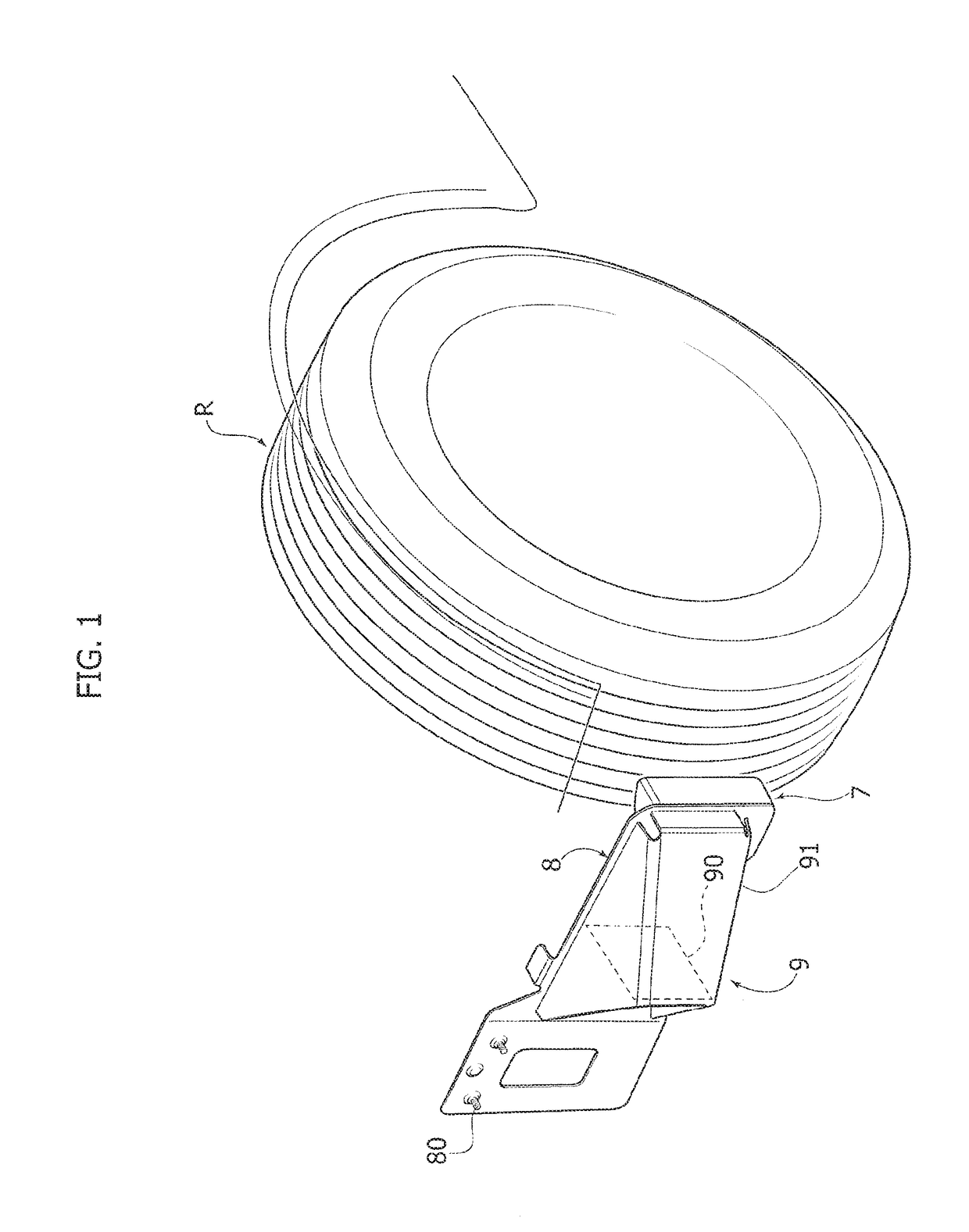
[0020]FIG. 1 is a perspective view of an embodiment of the device according to the invention,

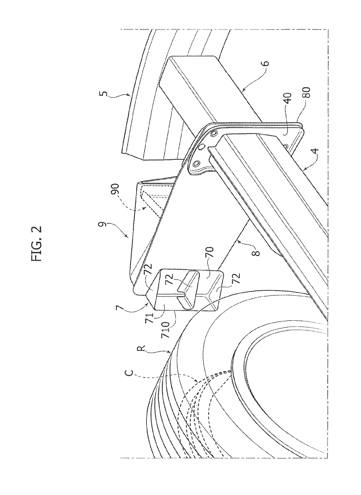
[0021]FIG. 2 is a further perspective view from below of the device of FIG. 1,

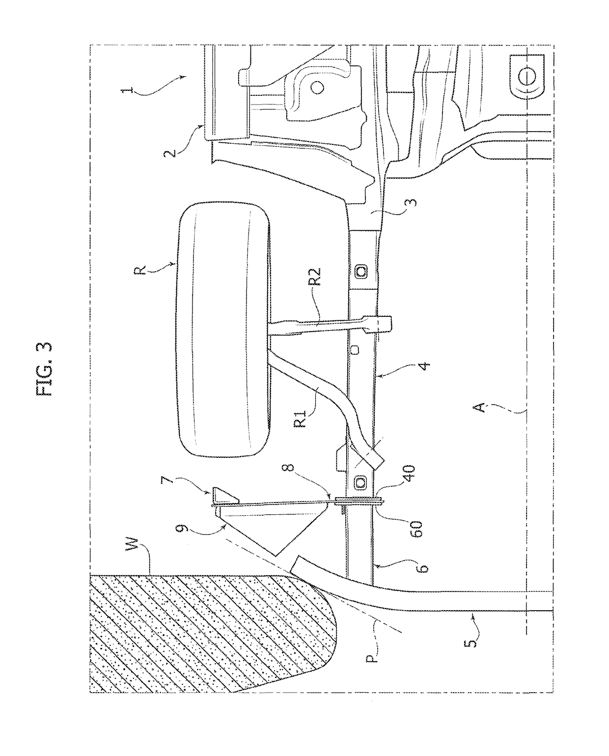
[0022]FIG. 3 is a view from below of one part of the structure of a motor-vehicle in an initial phase of a collision against the barrier,

[0023]FIG. 4 is a view at an enlarged scale of a detail of FIG. 3,

[0024]FIG. 5 is a further perspective view of the detail of FIG. 4, and

[0025]FIGS. 6 to 10 are plan views which show the subsequent phases of the operation of the safety device according to the invention, following a collision of the motor-vehicle against the barrier.

[0026]The annexed drawings show an exemplary application of the device according to the invention to a motor-vehicle having a front structure ...


PUM


Abstract

A safety device is described which is configured to orient a motor-vehicle front wheel transversely to the travel direction, following a collision of the motor-vehicle against a barrier. The device includes a ram member carried by a plate projecting laterally in a cantilever fashion from the motor-vehicle structure forwardly of the front wheel. The ram member is pushed against the front wheel following a collision of the motor-vehicle against the barrier. The ram member has a vertically elongated front portion, for engaging the wheel. With the transverse plate carrying the ram member there is associated a bumper structure located forwardly of the transverse plate and including a bumper element projecting forwardly from the transverse plate, at an intermediate position between the ram member and a connected end of the transverse plate.

Description

CROSS REFERENCE TO RELATED APPLICATIONS[0001]This application claims priority to European Patent Application No. 16165735.8 filed on Apr. 18, 2016, the entire disclosure of which is incorporated herein by reference.FIELD OF THE INVENTION[0002]The present invention relates to a safety device for orienting a motor-vehicle front wheel transversally to the longitudinal direction of the motor-vehicle following a collision of the motor-vehicle against a barrier. Devices of this type are being used for the purpose of increasing the degree of safety of the occupants of the motor-vehicle, particularly in the case of a collision with a reduced overlap between the vehicle and the barrier.PRIOR ART[0003]Document U.S. Pat. No. 9,067,617 B2 discloses a safety device of the above indicated type, comprising a ram-like member carried by the motor-vehicle structure forwardly of a motor-vehicle front wheel. The ram-like member is in a position such that it is pushed against said front wheel of the mot...

Claims


Application Information

Patent Timeline
Patent Type & Authority Patents(United States)
IPC IPC(8): B60R19/00B60R19/26B62D21/15B62D25/08B62D9/00B60R21/00
CPCB60R19/00B60R19/26B62D9/00B62D21/155B62D25/082B62D21/152B60R2021/0023B60R2019/005
Inventor CANOBBIO, MAURO GIACOMO ENRICOLAURINO, LUIGI
Owner FCA ITAL
Why Eureka
Try Eureka