Electrically driven power steering device

a technology of electric steering and steering wheel, which is applied in the direction of gearing, lifting equipment, transportation and packaging, etc., can solve the problems of tooth surface abrasion, dimensional error, and the amount of abrasion is on the increas

Active Publication Date: 2018-08-28
NSK LTD
View PDF25 Cites 2 Cited by
  • Summary
  • Abstract
  • Description
  • Claims
  • Application Information

AI Technical Summary

Benefits of technology

[0032]The biasing mechanism allows the tip side bearing to be displaced toward the worm wheel by the wedge surface and the guide surface by allowing the wedge piece to be displaced toward the one circumferential side of the annular space by the elastic force of the elastic member for a wedge piece.
[0040]In the case of the present invention, the guide surface and the wedge surface are in contact with two circumferential parts of the outer circumferential surface of the tip side bearing. Accordingly, components of the component of force within the virtual plane orthogonal to the worm shaft that pertain to the meshing reaction force applied to the worm shaft from the meshing portion and relate to the direction perpendicular to each of the meshing direction of the worm teeth and the worm wheel and the axial direction of the worm shaft can be borne by the guide surface and the wedge surface. Accordingly, a displacement of the tip side bearing in the perpendicular direction can be suppressed.
[0032]The biasing mechanism allows the tip side bearing to be displaced toward the worm wheel by the wedge surface and the guide surface by allowing the wedge piece to be displaced toward the one circumferential side of the annular space by the elastic force of the elastic member for a wedge piece.
[0042]As a result, the generation of a rattling noise that is attributable to a perpendicular vibration of the worm teeth in the meshing portion which is caused when rotational vibration is applied from a wheel side to the rotating shaft for steering can be suppressed.
[0043]When directions in which the guide surface and the wedge surface face the outer circumferential surface of the tip side bearing are regulated in predetermined directions, in particular, the component relating to the perpendicular direction can be efficiently borne by the guide surface and the wedge surface.
[0044]A perspective motion of the tip side bearing with respect to the worm wheel can be allowed based on an elastic deformation of the elastic member for a bearing or the elastic member for a guide piece in a case where the tip side bearing tends to exhibit the perspective motion with respect to the worm wheel as a result of a change in a meshing position of the worm teeth and the worm wheel based on a dimensional error in the direction of rotation of the worm shaft and the worm wheel during the rotation of the worm shaft and the worm wheel. As a result, a change in a biasing force of the worm teeth with respect to the worm wheel is suppressed, and a change in a frictional force that acts on the meshing portion is suppressed.

Problems solved by technology

This backlash results from an abrasion of a tooth surface of the worm wheel 4 and the worm teeth 5 as well as a dimensional error and an assembly error of each member constituting the worm-type speed reducer.
In recent years, in particular, the amount of the abrasion is on the increase and the backlash is becoming more and more likely to occur as the auxiliary power tends to be increased.

Method used


Image

  • Electrically driven power steering device
  • Electrically driven power steering device
  • Electrically driven power steering device

Examples


first embodiment

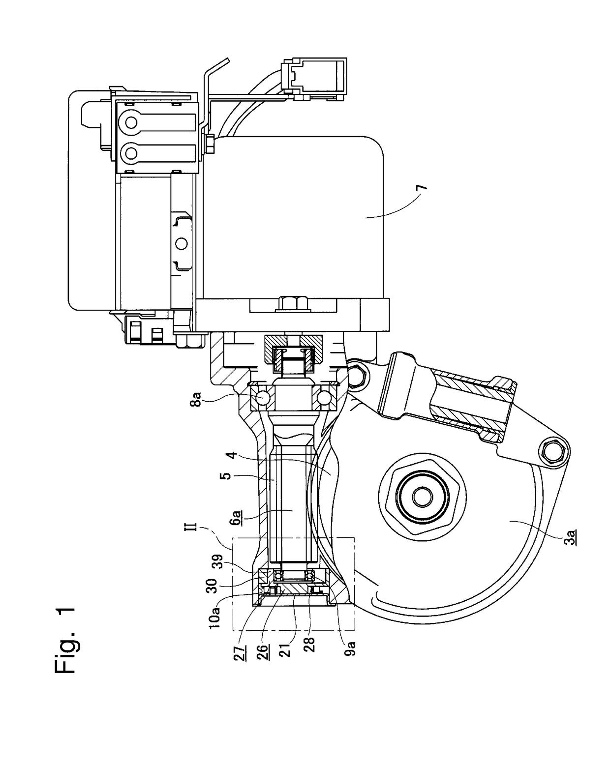
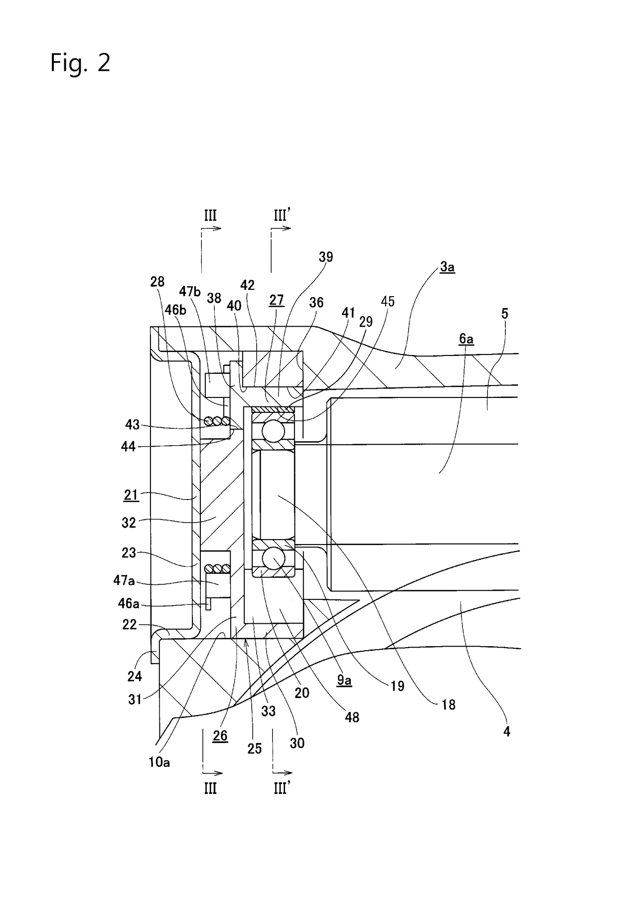
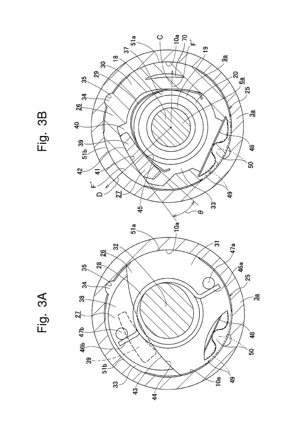
[0059]A first embodiment of the present invention will be described with reference to FIGS. 1 to 4.

[0060]A characteristic of an electric power steering device according to this embodiment consists in that a structure of biasing mechanism for biasing a tip portion of a worm shaft 6a toward a worm wheel 4 is devised. The structures and effects of the other parts are almost the same as those of the structure according to the prior art that is illustrated above with reference to FIGS. 10 and 11, and thus the following description will focus on characteristic parts of this embodiment with the illustration and description of the identical parts omitted or simplified. Although FIG. 11 described above and FIG. 1 for this embodiment differ from each other in terms of the direction in which an electric motor 7 is mounted on a housing 3a, it can be appropriately changed on a design basis depending on in-car installation, and thus has nothing to do with the characteristic parts of the present i...

second embodiment

[0079]A second embodiment of the present invention will be described with reference to FIGS. 5 and 6.

[0080]In the case of this embodiment, the configuration of biasing mechanism 25a is different in several points from that according to the first embodiment described above.

[0081]In the case of this embodiment, the outer circumferential surface of the outer ring 20 is in direct contact with the guide surface 37 and the wedge surface 45 instead of the leaf spring 29 for a bearing (refer to FIG. 3) being disposed between the outer circumferential surface of the outer ring 20 constituting the tip side bearing 9a and the guide surface 37 and between the outer circumferential surface of the outer ring 20 constituting the tip side bearing 9a and the wedge surface 45. Instead, in the case of this embodiment, a guide piece 30a constituting a guide member 26a is loosely and internally fitted into the inner circumferential surface of the holding recessed portion 10a of the housing 3a (a minute ...

third embodiment

[0085]A third embodiment of the present invention will be described with reference to FIGS. 7 and 8.

[0086]In the case of this embodiment, the configuration of biasing mechanism 25b is different in several points from that according to the first embodiment described above.

[0087]In the case of this embodiment, as illustrated in FIG. 8B, each of a guide piece 30b constituting a guide member 26b and a wedge member 27a formed only from a wedge piece 39a is formed to have a semi-cylindrical shape, and the guide piece 30b and the wedge piece 39a are arranged at positions on the sides opposite to each other in the radial direction in the annular space 33 which is present between the inner circumferential surface of the holding recessed portion 10a disposed in the housing 3a and the outer circumferential surface of the outer ring 20 constituting the tip side bearing 9a. In this state, circumferential gaps are disposed between both of respective circumferential end faces of the guide piece 30...


PUM


Abstract

An electric power steering device includes a housing, a rotating shaft for steering, a worm wheel, a worm shaft, a tip side bearing, an electric motor, and biasing mechanism. The biasing mechanism includes a wedge piece and an elastic member for a wedge piece. The wedge piece is disposed between an outer circumferential surface of the tip side bearing and an inner circumferential surface of the housing in a state where the wedge piece in a circumferential direction is displaceable. The elastic member for a wedge piece applies elastic force toward one circumferential side to the wedge piece.

Description

CROSS-REFERENCE TO RELATED APPLICATIONS[0001]This application is a National Stage of International Application No. PCT / JP2015 / 062574 filed Apr. 24, 2015, claiming priority based on Japanese Patent Application No. 2014-181961 filed Sep. 8, 2014, and Japanese Patent Application No. 2015-025910 filed Feb. 13, 2015, the contents of all of which are incorporated herein by reference in their entirety.TECHNICAL FIELD[0002]The present invention relates to an electric power steering device and, more particularly, to an electric power steering device that is used as an automotive steering device and reduces a force required for a driver's steering wheel operation by using an electric motor as an auxiliary power source. In particular, the present invention relates to a technique for suppressing the generation of an uncomfortable and abnormal noise called a rattling noise at a worm-type speed reducer part that constitutes the electric power steering device.BACKGROUND ART[0003]A power steering d...

Claims


Application Information

Patent Timeline
Patent Type & Authority Patents(United States)
IPC IPC(8): B62D5/04F16H1/16F16H55/24
CPCB62D5/0409F16H55/24F16H1/16B62D5/0454F16C19/26F16C25/06F16C2326/24
Inventor SEGAWA, TORU
Owner NSK LTD
Why Eureka
Try Eureka