
Floating feed assist unit for the payoff of bulk packaged welding wire

a technology of welding wire and assist unit, which is applied in the direction of welding apparatus, manufacturing tools, transportation and packaging, etc., can solve the problems of excess or loose wire in the drum, tangle of wire, and progressively forced back into the drum

Active Publication Date: 2018-08-28
ALCOTEC WIRE
View PDF35 Cites 1 Cited by
  • Summary
  • Abstract
  • Description
  • Claims
  • Application Information

AI Technical Summary

Benefits of technology

The patent describes a system for delivering welding wire from bulk drums effectively and smoothly. The system helps to remove the wire from the drum and feed it through a welding system. It works well with both hard and soft aluminum alloys, as well as wires made from various materials. The system ensures consistent and untangled wire pay-off.

Problems solved by technology

The most significant issue in dispensing wire of this type is the problem of tangling of the wire during the payoff process.
This problem is further increased with the use of a new product in the welding industry often referred to as “roller liner.” Wire packaged in drums has an inherent twist in the wire, which is similar to the twist found in a garden hose that is coiled up on the ground.
This results in the twist being progressively forced back into the drum.
Any excess or loose wire in the drum can become tangled in such a situation.
This can be a problem for both 5xxx and 4xxx alloys.
Unfortunately, this did little to prevent the twisting associated with the “roller liner.”
This design fails to provide a sufficient amount of friction on the wire.
The orbital arm and the steel ring failed as a result of there being too much loose wire in the drum.
The other payoff devices lack the appropriate amount of pressure and friction on the wire stack.
This results in excessive amounts of wire being drawn from under that payoff unit.
The excessive wire combined with the twisting resulting from the “roller liner” still causes tangling.
This bend fails to optimally feed the wire from the stack.

Method used


Image

  • Floating feed assist unit for the payoff of bulk packaged welding wire
  • Floating feed assist unit for the payoff of bulk packaged welding wire
  • Floating feed assist unit for the payoff of bulk packaged welding wire

Examples


Embodiment Construction

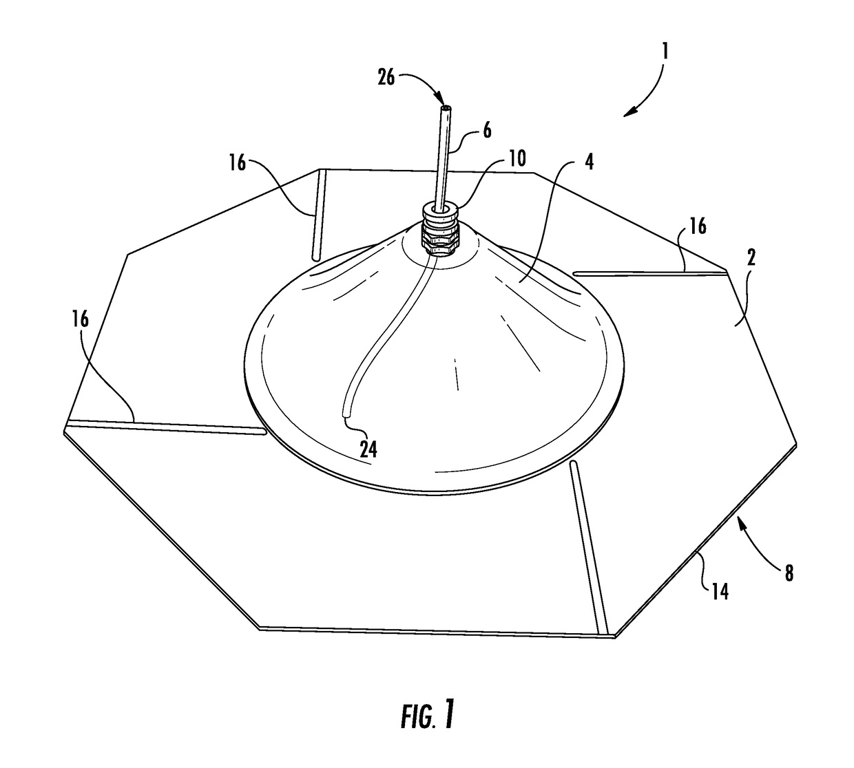
[0030]The disclosed feed assist unit is configured to float on a wire stack, and includes a rotating conduit sleeve for guiding the unwinding wire out of its container. Ribs are provided on the underside of the feed assist unit to provide point contact on the wire of the stack, thus enabling the wire to be consistently pulled off the stack in small amounts, thereby preventing the unraveling of large sections of loose wire that could tangle.

[0031]The rotating section of conduit is formed in such a way as to lift the wire from the stack in a natural manner. In one embodiment the rotating conduit section is bent in two dimensions to best achieve this goal. The disclosed system ensures that the wire is still able to feed freely without a large amount of friction creating tension in the system.

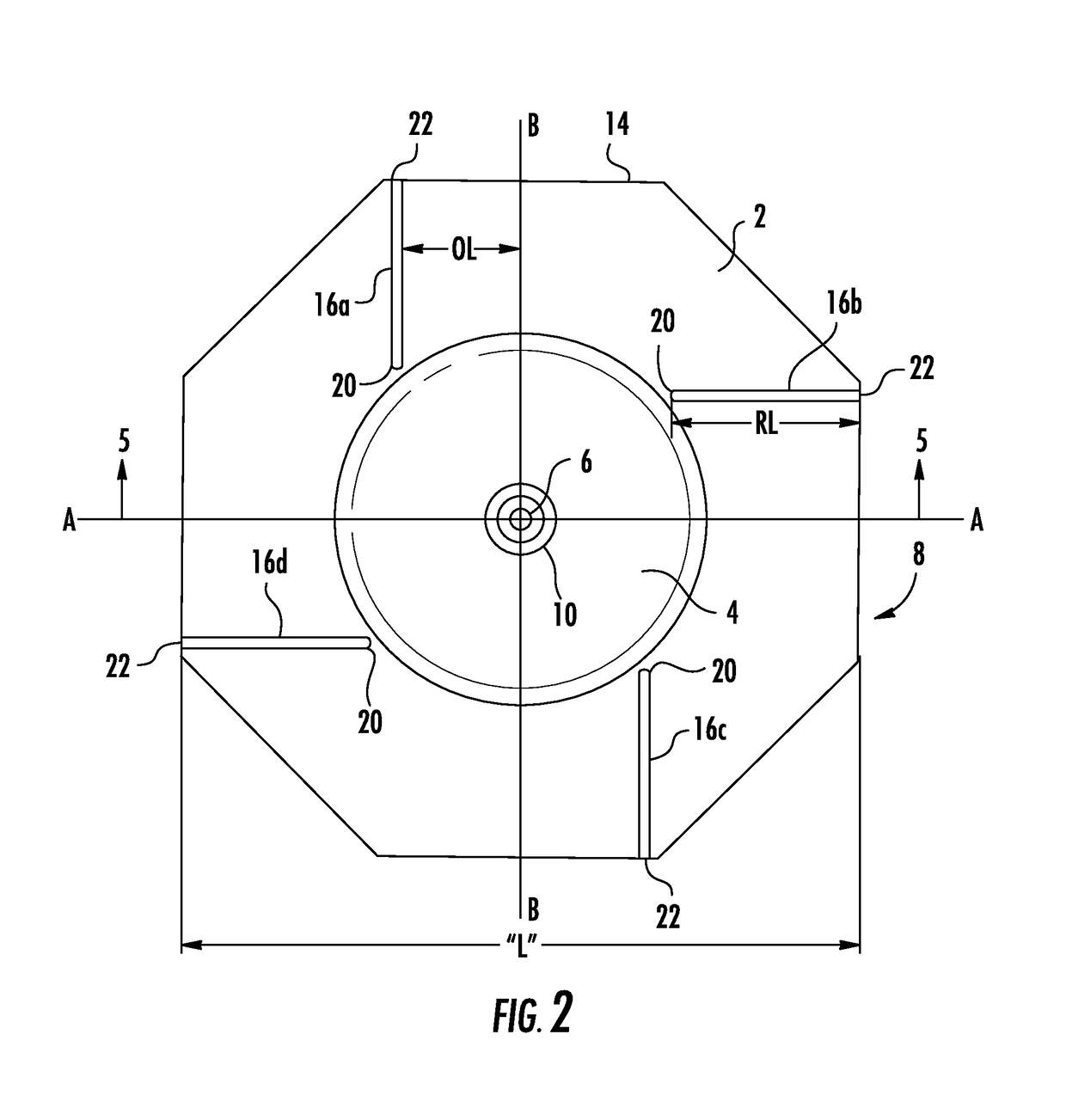
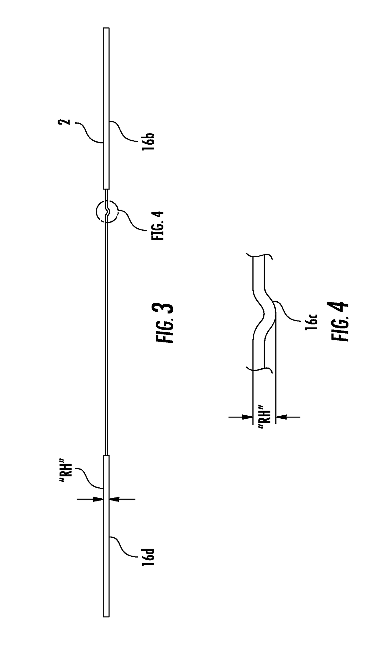
[0032]Referring to FIGS. 1-6, the feed assist unit 1 comprises a base portion 2, a dome portion 4 and a rotatable conduit portion 6. The base portion 2 may be generally planar and may support the d...


PUM

PropertyMeasurementUnit
side lengthaaaaaaaaaa
heightaaaaaaaaaa
lengthaaaaaaaaaa

Abstract

A feed assist unit (1) includes a base portion (2) having a plurality of ribs (16a-d) on a lower surface (18) thereof. A dome portion (4) is connected to the base portion (2), and a rotating conduit portion (6) has a curved shape and is coupled to the dome portion (4). Each of the ribs (16a-d) has a first end (20) adjacent to the dome portion (4) and a second end (22) adjacent an associated side (14) of the base portion (2). The feed assist unit (1) has first and second central axes (A-A, B-B) oriented perpendicular to each other. First and third of the ribs (16a, 16c) are oriented parallel to the second central axis (B-B) and the second and fourth of the ribs (16b, 16d) can be oriented parallel to the first central axis (A-A). The first and third ribs (16a, 16c) are offset from the second central axis (B-B) by an offset length (OL) and the second and fourth ribs (16b, 16d) are offset from the first central axis (A-A) the offset length (OL).

Description

CROSS-REFERENCE TO RELATED APPLICATIONS[0001]This is a non-provisional of provisional application Ser. No. 62 / 033,742, filed Aug. 6, 2014, the entirety of which application is incorporated by reference herein.BACKGROUND OF THE DISCLOSURE[0002]Field of the Disclosure[0003]Embodiments of the invention generally relate to the dispensing of welding wire, and more particularly to a system and method for facilitating the dispensing of welding wire from a container.[0004]Discussion of Related Art[0005]There are unique dynamics that accompany the dispensing of welding wire from a bulk package such as a drum. The drums of wire require special payoff considerations in comparison to the contrasting method of using spools. For example, it may be important to maintain downward pressure on the wire while dispensing. This pressure should be light enough to ensure that it does not inhibit the feeding of the wire, which should be smooth and consistent. However, the downward pressure should be suffic...

Claims


Application Information

Patent Timeline
Patent Type & Authority Patents(United States)
IPC IPC(8): B65H57/20B65H57/18B23K9/133B65H49/08
CPCB65H57/20B23K9/1333B65H57/18B65H49/08B65H2701/36
Inventor PFALLER, THOMAS LEOKRAUSE, ROBERT ALLEN
Owner ALCOTEC WIRE
Learn More