Pyrotechnic actuator mechanism, syringe and igniter assembly

a technology of pyrotechnic actuators and actuators, which is applied in the direction of pyrotechnic actuators, infusion syringes, weapons, etc., can solve the problems of large pressure easily exerted by the high combustion energy and the contained combustion residue, and the inability to sufficiently suppress the discharge or emission of the residue to the outside, so as to reduce the number of constitutive parts

Active Publication Date: 2018-08-28
DAICEL CHEM IND LTD
View PDF16 Cites 8 Cited by
  • Summary
  • Abstract
  • Description
  • Claims
  • Application Information

AI Technical Summary

Benefits of technology

[0015]On the other hand, the second wall member is the wall member which is connected to the first wall member. Therefore, when the first wall member receives the force in accordance with the combustion of the ignition charge as described above, the second wall member is also moved in accordance therewith in the direction in which the first wall member is separated from the ignition unit. In this situation, the free end portion of the second wall member is in the state of being embedded in the fixing member. However, the free end portion is not consequently in a state in which the free end portion is fixed by the fixing member. Therefore, the separation from the ignition unit is not inhibited when the ignition charge is combusted. In other words, the free end portion of the second wall member is fixed to such an extent that the free end portion can be moved by receiving the combustion energy of the ignition charge. On the other hand, the free end portion of the second wall member is embedded in the fixing member, and thus the hermetic sealing performance of the predetermined closed space described above, i.e., the ability to suppress the discharge or emission of the combustion product of the ignition charge is secured or guaranteed.
[0029]It is possible to provide the technique which preferably suppresses the discharge or emission of the residue produced by the combustion of the ignition charge to the outside.

Problems solved by technology

However, the residue is produced when the ignition charge is combusted.
However, if it is intended to seal the combustion product of the ignition charge in the certain space by means of the bag such as the sack or the like as mentioned in Patent Literature 1 and Patent Literature 2 described above, the relatively large pressure is easily exerted by the high combustion energy and the contained combustion residue.
Further, it is impossible to sufficiently suppress the discharge or emission of the residue to the outside by merely adjusting the clearance as mentioned in Patent Literature 3.

Method used


Image

  • Pyrotechnic actuator mechanism, syringe and igniter assembly
  • Pyrotechnic actuator mechanism, syringe and igniter assembly
  • Pyrotechnic actuator mechanism, syringe and igniter assembly

Examples


first embodiment

10>

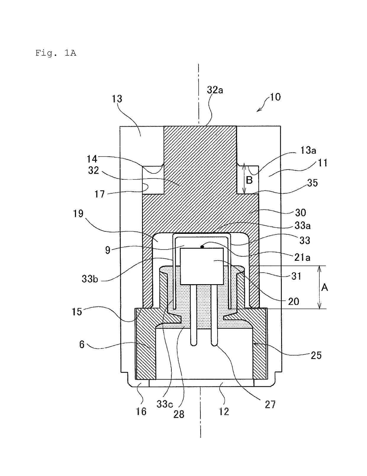
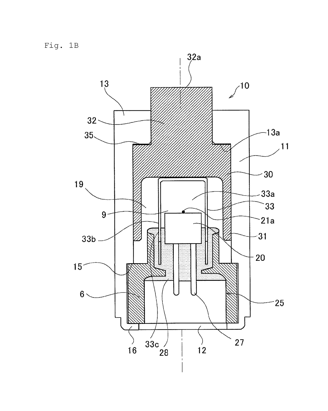
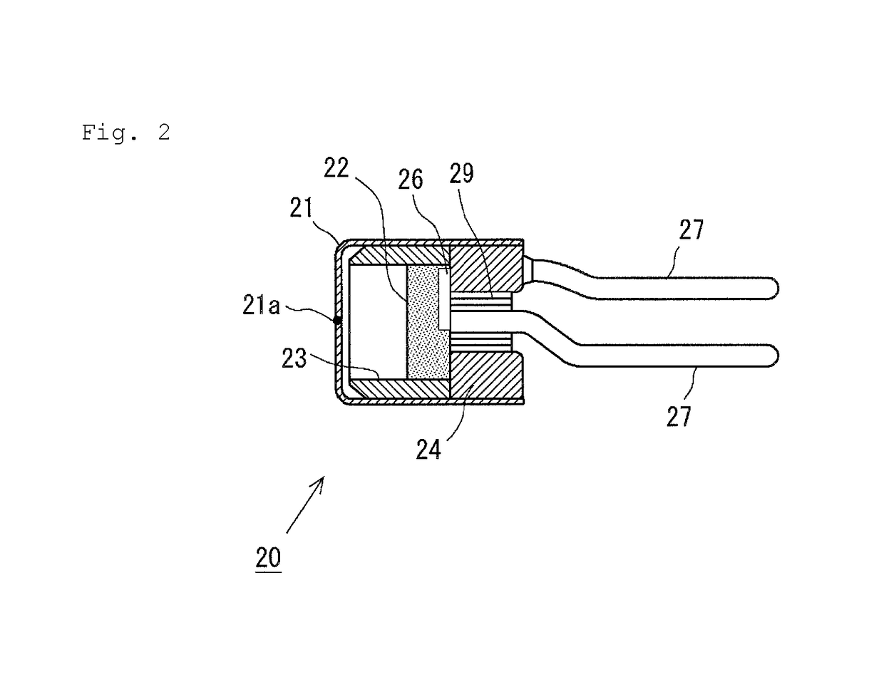
[0038]FIG. 1A shows a schematic structure of a pyrotechnic actuator mechanism 10 according to the present disclosure (hereinafter simply referred to as “actuator mechanism”), illustrating a structure provided in a state before the combustion of an ignition charge, in a vertical cross section of the actuator mechanism 10. Further, FIG. 1B shows a schematic structure of the actuator mechanism 10 provided in a state after the combustion of the ignition charge, in a vertical cross section thereof. Further, FIG. 2 shows a schematic structure of an ignition unit 20 included in an igniter 25 of the actuator mechanism 10.

[0039]A housing 11 of the actuator mechanism 10 has a circular cross section. An electric ignition igniter 25 (hereinafter simply referred to as “igniter”) is attached to an opening 12 disposed on one end side. The igniter 25 has an ignition unit 20 which includes the ignition charge. An example of the ignition unit 20 will now be explained on the basis of FIG. 2. In the...

second embodiment

[0052]Next, an explanation will be made on the basis of FIGS. 3A and 3B about a syringe 40 which uses the pyrotechnic actuator mechanism according to the present disclosure (hereinafter simply referred to as “actuator mechanism” as well) as the driving source. The actuator mechanism has substantially the same operation principle as that of the actuator mechanism 10 described in the first embodiment. In this context, FIG. 3A shows a schematic structure of the syringe 40, illustrating a structure in a state before the combustion of the ignition charge in the actuator mechanism, in a vertical cross section of the syringe 40. Further, FIG. 3B shows a schematic structure of the syringe 40 in a state after the combustion of the ignition charge, in a vertical cross section thereof.

[0053]Note that in the following description of this specification, the injection objective substance, which is to be injected into an injection target area by the syringe 40, is generally referred to as “injecti...

third embodiment

[0065]Next, an igniter assembly 60 according to the present disclosure will be explained on the basis of FIG. 4. The igniter assembly 60 is an assembly which is incorporated into the pyrotechnic actuator mechanism according to the present disclosure and which includes an ignition unit to cause the combustion of the ignition charge. The ignition unit 61, which is included in the igniter assembly 60, is substantially the same as the ignition unit 20 described in the first embodiment and the ignition unit 41 described in the second embodiment, any detailed explanation of which is omitted (see FIG. 2). Then, in the igniter assembly 60, the ignition unit 61 is fixed to a mold portion 64 formed of resin. Further, a cover member 62 is temporarily fixed to the mold portion 64 so that the release portion of the cup of the ignition unit 61 for releasing the combustion product is covered therewith. Note that the mold portion 64 of this embodiment corresponds to the mold portion 28 of the first...


PUM


Abstract

A pyrotechnic actuator mechanism comprises a cover member which includes a first wall member which is opposed to a release portion of an ignition unit, and a second wall member which is connected thereto and which has a free end portion embedded in a fixing member. When an ignition charge contained in the ignition unit is combusted, then the cover member is moved in the propulsion direction so that a predetermined closed space is expanded in the propulsion direction of a piston, and the movement of the cover member is regulated so that a state, in which the free end portion of the second wall member is embedded in the fixing member, is maintained at a maximum propulsion position of the cover member. Accordingly, the residue, which is produced by the combustion of the ignition charge, is preferably suppressed from being discharged or emitted to the outside.

Description

CROSS-REFERENCE TO RELATED APPLICATIONS[0001]This application is a continuation application, and claims the benefit under 35 U.S.C. §§ 120 and 365 of PCT Application No. PCT / JP2016 / 054481, filed on Feb. 16, 2016, which is hereby incorporated by reference. PCT / JP2016 / 054481 also claimed priority from Japanese Patent Application No. 2015-029074 filed on Feb. 17, 2015, the entire contents of which are incorporated by reference.TECHNICAL FIELD[0002]The present disclosure relates to a pyrotechnic actuator mechanism which obtains an output by means of the combustion of an ignition charge, a syringe which utilizes the same, and an igniter assembly which is usable in order to ignite or inflame the ignition charge.BACKGROUND ART[0003]A pyrotechnic actuator mechanism, which is an actuator mechanism to obtain an output by moving a piston by means of the force of an ignition charge, is used for apparatuses including, for example, an airbag system for vehicles, a pedestrian protection system, a ...

Claims


Application Information

Patent Timeline
Patent Type & Authority Patents(United States)
IPC IPC(8): F15B15/19F42B3/04F42B3/12A61M5/30
CPCF15B15/19F42B3/12F42B3/04A61M5/30A61M5/2046F42B3/006
Inventor YAMADA, RYOHEIMASUMOTO, TAKAYA
Owner DAICEL CHEM IND LTD
Why Eureka
Try Eureka