
Sheet manufacturing apparatus

Active Publication Date: 2019-04-02
SEIKO EPSON CORP
View PDF11 Cites 0 Cited by
  • Summary
  • Abstract
  • Description
  • Claims
  • Application Information

AI Technical Summary

Benefits of technology

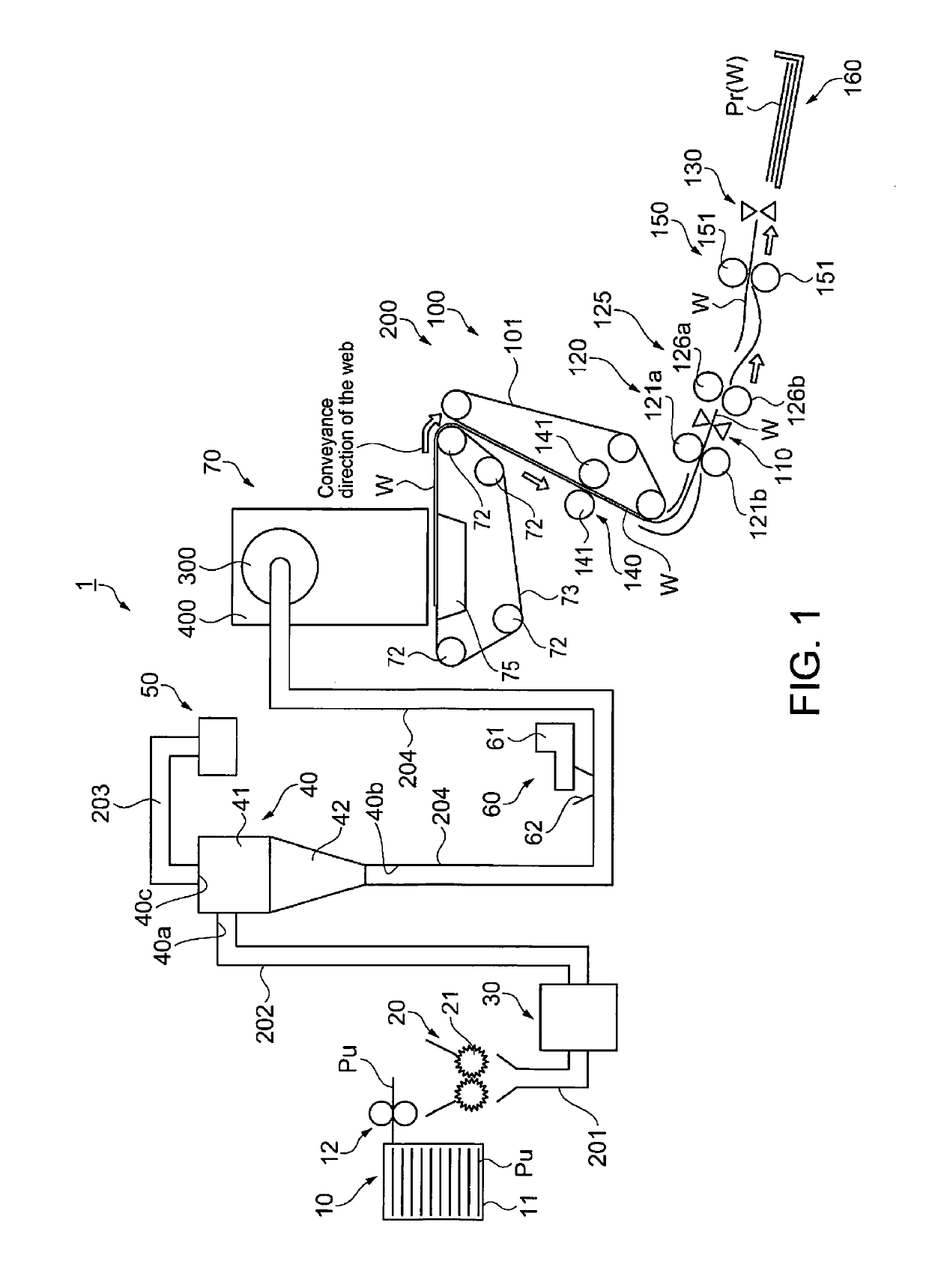
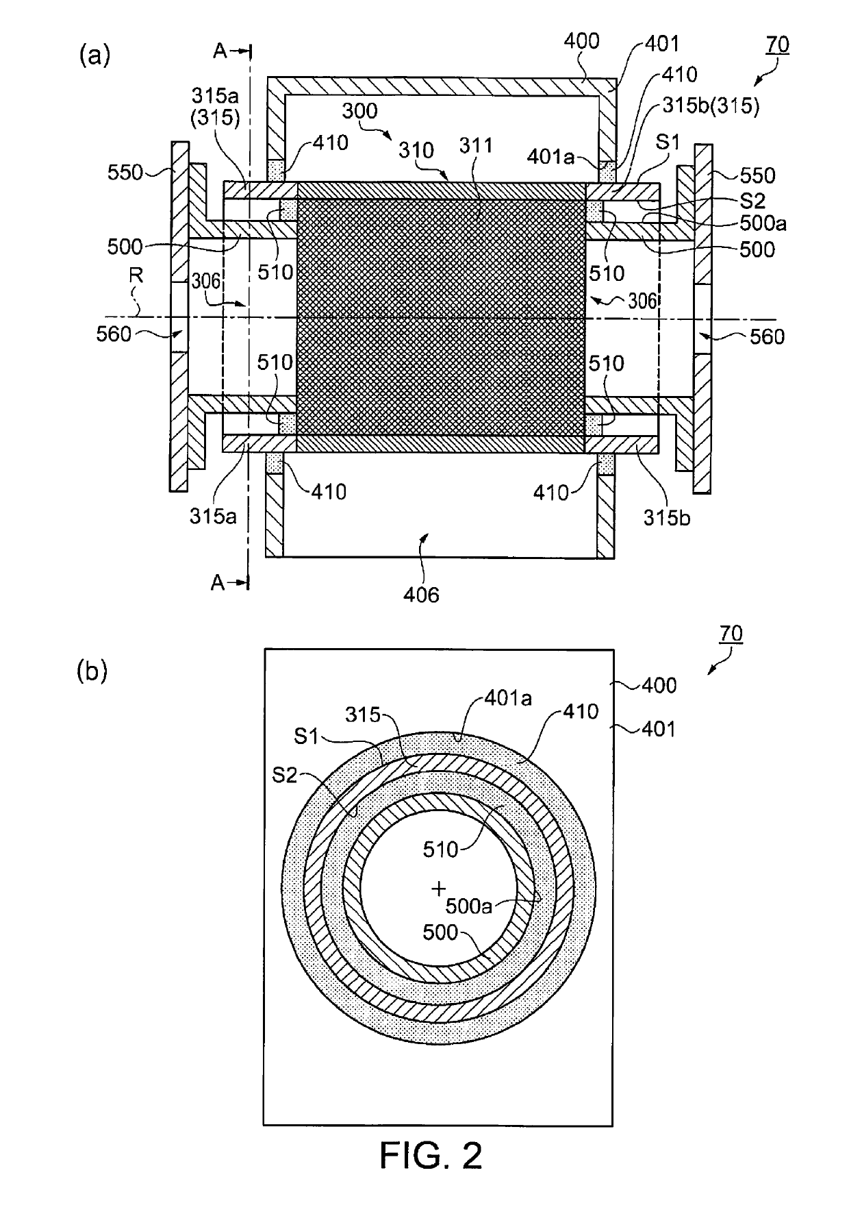
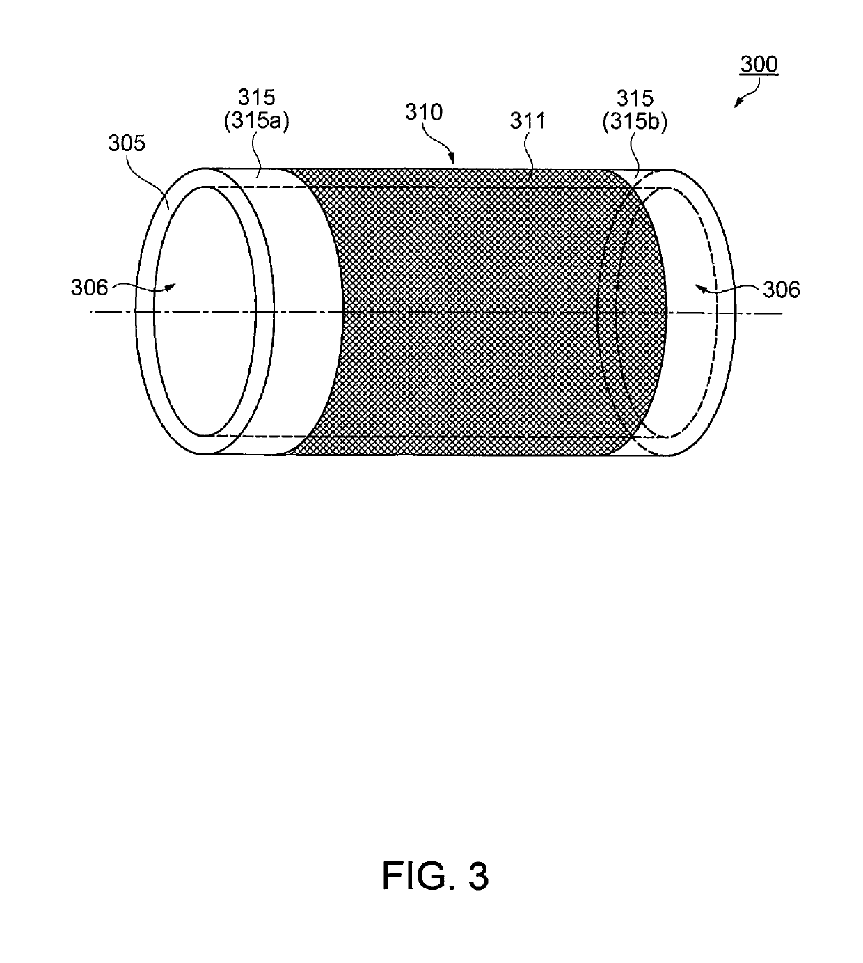
The invention is a device for manufacturing sheets with constant thickness. The device includes a screen and a cylinder section that is enclosed by a housing unit. The cylinder section is in mutual contact with the housing unit, which reduces the length of the housing unit and makes the device more compact. The housing unit also contacts the outer surface of the cylinder sections, which prevents material from leaking out of the housing unit. A pile seal is also used to prevent fiber discharge and improve durability. These technical features enable the manufacturing of sheets with constant thickness.

Problems solved by technology

As a result, what type of structure can be used to suppress such material from spreading is unknown.

Method used


Image

  • Sheet manufacturing apparatus
  • Sheet manufacturing apparatus
  • Sheet manufacturing apparatus

Examples


example 1

[0066]The distributor unit 70 in the foregoing embodiment is configured with a flange unit 500 inside the cylinder section 315, but the invention is not so limited. For example, configurations having the flange unit disposed outside the cylinder section 315 are also conceivable. FIG. 5 schematically illustrates the configuration of the distributor unit in example 1. As shown in FIG. 5, the distributor unit 70a according to example 1 has a drum unit 300 and housing 400. The configurations of the drum unit 300, housing 400, and pile seal strip 410 are as described in the embodiment described above, and further description thereof is omitted.

[0067]In this example as shown in FIG. 5, there is a stationary flange unit 501 on the outside of the cylinder section 315 of the drum unit 300, and the cylinder section 315 and the flange unit 501 are in contact through the second pile seal strip 510. In this example, the flange unit 501 is outside the cylinder sections 315a, 315b of the drum unit...

example 2

[0069]The distributor unit 70 in the foregoing embodiment is configured with a flange unit 500 inside the cylinder section 315, but the invention is not so limited. For example, configurations in which the flange unit 500 is omitted are also conceivable. FIG. 6 schematically illustrates the configuration of the distributor unit in example 2. As shown in FIG. 6, the distributor unit 70b according to example 2 has a drum unit 300a and housing 400. As described in the foregoing embodiment, the drum unit 300a in this example has a screen 310 with numerous apertures 311, and a cylinder section 315 without apertures 311. The drum unit 300a in this example has a neck 320 that reduces the inside diameter of the drum unit 300a formed at each end of the drum unit 300a on the axis of rotation R, and an opening 306a is formed in each neck 320. The opening 306a functions as the material supply port through which is supplied into the drum unit 300a.

[0070]The housing 400 has a pile seal strip 410...

example 3

[0071]A drive unit for turning the drum unit 300 is not shown in the figures of the foregoing embodiment. The drive unit has a gear disposed to the cylinder section 315 outside of the housing 400 (outside of the part that contacts the pile seal strip 410) in FIG. 2, FIG. 5, and FIG. 6, and drives by means of a belt and gears, A gear may be used on the neck 320 in FIG. 6. By placing the drive unit outside the housing 400, being caught in the drive unit and causing drive problems and increasing the drive load can be suppressed.


PUM


Abstract

A drum unit includes a screen with numerous apertures through which airborne material including at least fiber passes, and a cylinder section without apertures, disposed to a rotating cylinder; a housing unit encloses the screen part of the drum unit inside and contacts the cylinder section; and a forming unit forms sheets using material that passes through the apertures.

Description

CROSS-REFERENCE TO RELATED APPLICATIONS[0001]This application is a U.S. National stage application of International Patent Application No. PCT / JP2014 / 004434, filed on Aug. 28, 2014, which claims priority under 35 U.S.C. § 119(a) to Japanese Patent Application No. 2013-266609, filed in Japan on Dec. 25, 2013. The entire disclosure of Japanese Patent Application No. 2013-266609 is hereby incorporated herein by reference.BACKGROUND OF THE INVENTIONField of the Invention[0002]The present invention relates to a sheet manufacturing apparatus.Background Information[0003]A paper recycling system having a dry defibrating unit that shreds and defibrates paper, a first conveyance unit that conveys the defibrated material output by the dry defibrating unit, an air classifier that separates and deinks the defibrated material conveyed by the first conveyance unit, a second conveyance unit that conveys the defibrated material de-inked by the classifier, and a paper-forming unit that produces paper...

Claims


Application Information

Patent Timeline
IPC IPC(8): D21B1/06D04H1/732D21F9/00D04H1/26D04H1/72D04H1/736D21B1/08B27N3/12
CPCD21B1/06D04H1/26D04H1/732D21F9/00D21B1/08B27N3/12D04H1/72D04H1/736
Inventor MIYAZAWA, KAZUMAFUJITA, SHIGEO
Owner SEIKO EPSON CORP
Learn More