Linear vibrator

a vibrator and linear technology, applied in the field of vibrators, can solve the problem of not maximizing the use ratio of the magnetic field by the voice coil

Active Publication Date: 2018-08-28
AAC TECH PTE LTD
View PDF20 Cites 21 Cited by
  • Summary
  • Abstract
  • Description
  • Claims
  • Application Information

AI Technical Summary

Benefits of technology

[0021]After the voice coil 12 is energized, the voice coil 12 is under the Lorentz force in the magnetic field of the magnet array 14. The reaction force of the voice coil 12 enables the magnet array 14 to produce a thrust along its long axis. The mass block 13 and the first soft magnetic plate 15 are vibrated at the same time. Since the longitudinal magnetization of the first magnet 141 and the transverse magnetization of the second magnet 142 of the magnets 14 are arranged alternately, the magnetic fields on both sides of the magnet array 14 are distributed unevenly. The magnetic field at the side close to the voice coil 12 is increased and the magnetic field of the side far from the voice coil 12 is reduced, as a result, the magnetic field strength at the side close to the voice coil 12 is stronger than the magnetic field strength at the side far from the voice coil 12, thereby increasing the utilization ratio of the magnetic field by the voice coil 12. The increased magnetic field strength of the magnets 14 at the side close to the voice coil 12 can increase the driving force of the linear vibrator If the driving force keeps constant, the size of the magnets can be reduced; thereby the entire size of the linear vibrator can be further reduced, more conducive to the miniaturization of linear vibrator Furthermore, the reduced magnetic field strength of the magnet array 14 at the side far from the voice coil 12 can reduce the magnetic-flux leakage at this side.

Problems solved by technology

However, because only the magnetic field lines at one side of the magnet pass through the voice coil, the utilization ratio of the magnetic field by the voice coil is not maximized.

Method used


Image

  • Linear vibrator
  • Linear vibrator
  • Linear vibrator

Examples


Embodiment Construction

[0010]The present invention will hereinafter be described in detail with reference to an exemplary embodiment. To make the technical problems to be solved, technical solutions and beneficial effects of present disclosure more apparent, the present disclosure is described in further detail together with the figures and the embodiment. It should be understood the specific embodiment described hereby is only to explain this disclosure, not intended to limit this disclosure.

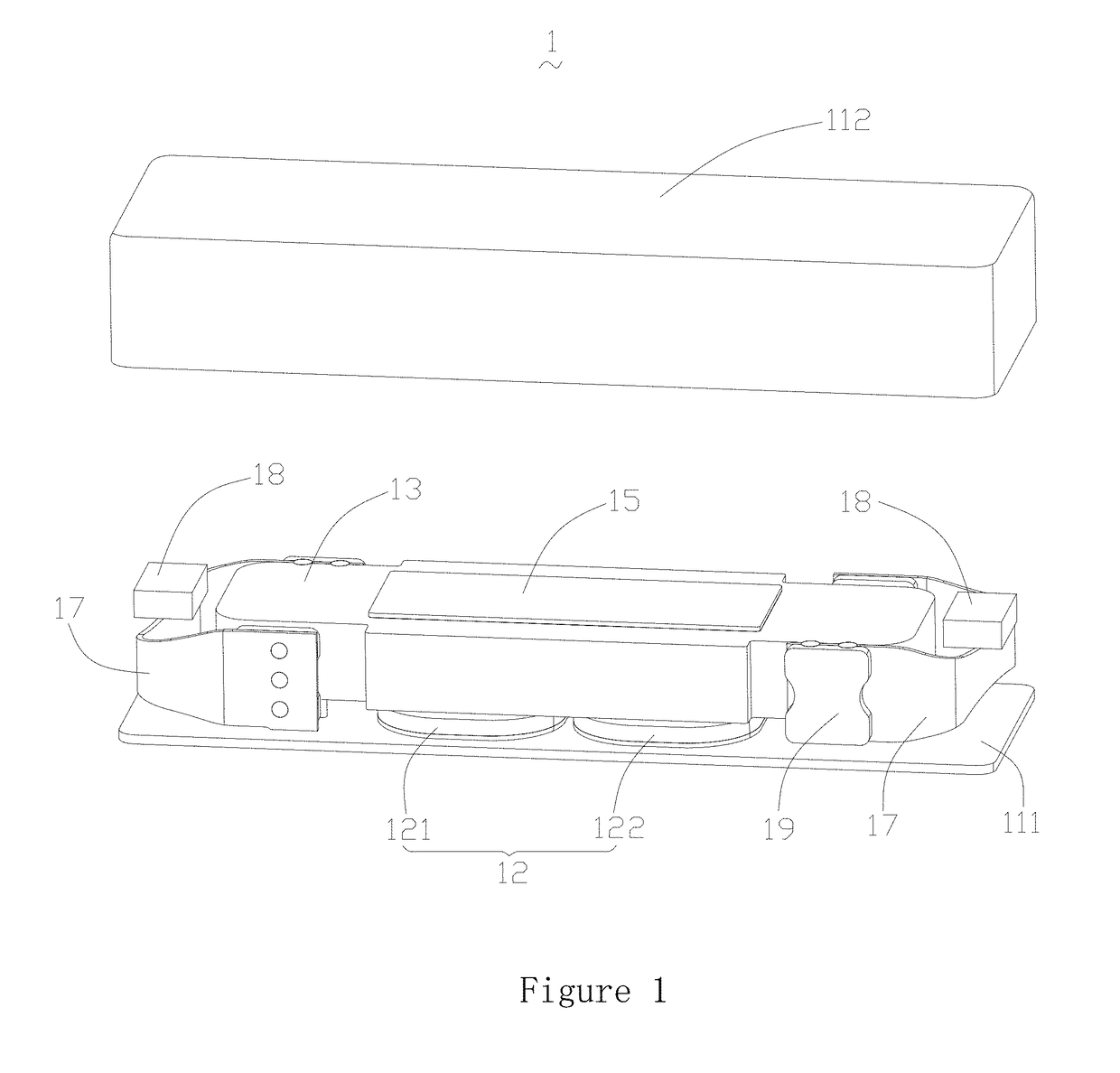
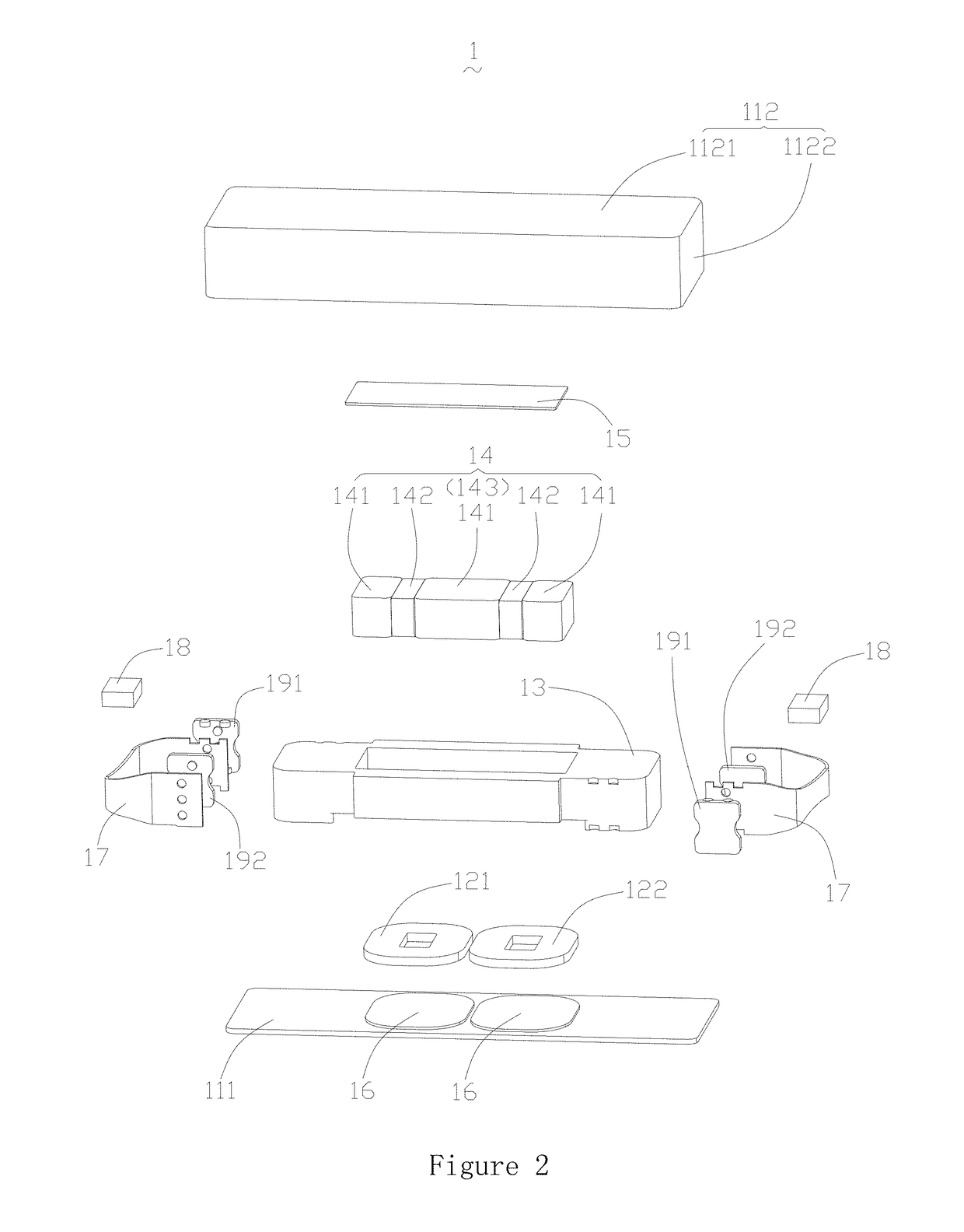
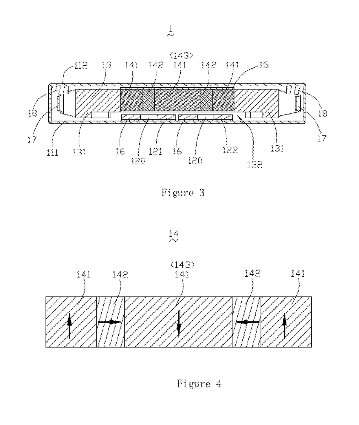
[0011]Please refer to FIGS. 1, 2 and 3. FIG. 1 is an isometric view of a linear vibrator in accordance with an exemplary embodiment disclosed by the present disclosure. FIG. 2 is an isometric and exploded view of the linear vibrator in FIG. 1. FIG. 3 is a cross-sectional view of the linear vibrator in FIG. 1. The linear vibrator 1 comprises a housing body (not labeled), a voice coil 12, a mass block 13 with a receiving space, a magnet array 14, a first soft magnetic plate 15, a second soft magnetic plate 16, a pair o...


PUM


Abstract

The present disclosure relates to a linear vibrator including a bottom plate, a voice coil fixed on the bottom plate, a mass block which has a receiving space and located above the voice coil, a magnet array in the receiving space, the magnet array including odd number of longitudinally magnetized first magnets and even number of transversely magnetized second magnets, the first magnets and the second magnets being arranged alternately in a row, and the adjacent first magnets in opposite magnetization direction and the adjacent second magnets in opposite magnetization direction.

Description

FIELD OF THE INVENTION[0001]The present invention relates to the field of vibrators, particularly to a linear vibrator for a mobile terminal device.DESCRIPTION OF RELATED ART[0002]Consumer products, such as mobile phones and portable multi-media players, generally include vibrators for generating tactile feedback. For example, a mobile phone has a vibrator for generating vibration while a call is called in, and a portable multi-media player has a touch screen having vibrators for getting tactile feedback.[0003]For a linear vibrator vibrating along a longitudinal direction, it usually includes three magnets, soft magnetic material and two voice coils to form magnetic circuit. Three magnets are arranged side by side and the magnetic induction intensity at the end of the magnets is same. The magnetic field lines close to the voice coil pass through the voice coil so that the voice coil is driven by Lorentz force while electrified. The magnetic lines at the side far away the voice coil ...

Claims


Application Information

Patent Timeline
Patent Type & Authority Patents(United States)
IPC IPC(8): H02K33/16
CPCH02K33/16
Inventor WANG, HONGXINGHOU, FEIMAO, LUBINGUO, SHUN
Owner AAC TECH PTE LTD
Why Eureka
Try Eureka