Wireless sensor networks

a sensor network and wireless technology, applied in the field of wireless sensor networks, can solve the problems of reducing battery life, reducing battery life, and increasing cost and weight, and achieve the effect of prolonging battery life and high degree of flexibility

Active Publication Date: 2018-09-11
DRAGER SAFETY
View PDF25 Cites 0 Cited by
  • Summary
  • Abstract
  • Description
  • Claims
  • Application Information

AI Technical Summary

Benefits of technology

[0006]Thus it will be seen by those skilled in the art that in accordance with the invention, a remote sensor may have a relatively low update rate (derived from the deliberate delay in responding to the interrogation message) under normal circumstances but it is nonetheless able to report more quickly in the event of an alarm condition being met. This gives the benefit of longer battery life for a remote sensor unit whilst retaining its ability to be used in safety-critical systems. The feature of deliberately delaying the reply under normal conditions but sending it sooner under an alarm condition is advantageous as it enables the sensor unit to have control over when the reply is sent but is compatible with protocols where a remote sensor unit can only respond to interrogation messages; i.e. it cannot initiate a communication.
[0018]As a corollary to this the interrogating node may comprise a sensor for sensing a parameter such that the interrogating node can itself detect and report an alarm condition without having to communicate with a further interrogating node.
[0019]Preferably the sensor unit is battery powered. This allows a high degree of flexibility in where it is placed. It need not be powered exclusively by one or more batteries; it may also comprise solar cells or other energy harvesting sources to extend battery life. Multiple sensor units could share a power source.
[0023]The deliberate delay in the sensor unit is preferably arranged so that the reply to the interrogation message is sent shortly before the next interrogation message is received—in other words the deliberate delay is as long as possible without overlapping the next message. This maximises the advantage achievable in accordance with the invention of being able to send an alarm message as the reply as quickly as possible if an alarm condition is detected. It also advantageously allows the sensor unit to go into a sleep state between reception of the interrogating message and transmission of the reply so that it only has to wake up once each cycle. In the sleep state the sensor unit need only monitor for the alarm condition and carry out any other essential functions but can switch off the circuitry related to the transmitter and receiver.

Problems solved by technology

However there are some applications where timing is critical to safety.
This can be achieved by using a high update rate but this comes at the cost of a significant increase in power consumption and therefore consequent reduction in battery life or increase in cost and weight.

Method used


Image

  • Wireless sensor networks
  • Wireless sensor networks
  • Wireless sensor networks

Examples


Embodiment Construction

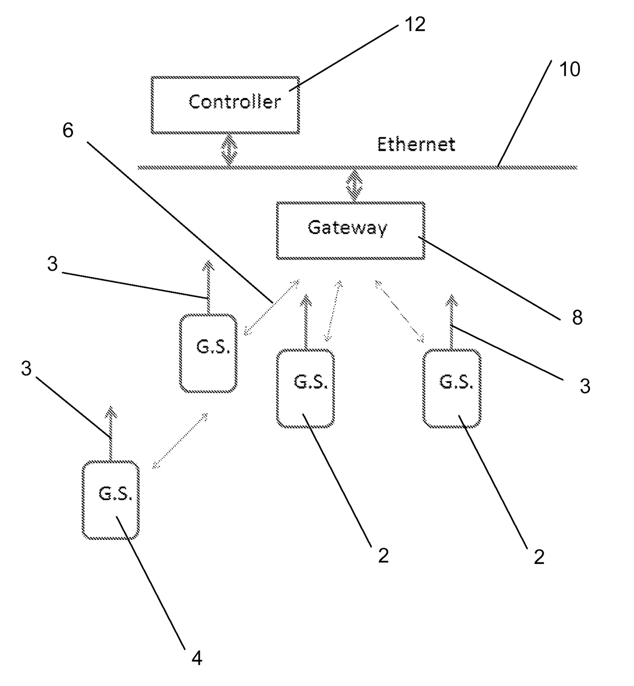
[0034]Referring first to FIG. 1, there can be seen a network of hydrocarbon gas sensor units 2, 4. Each of the sensor units 2, 4 comprises a gas detector and a 2.4 GHz radio transmitter and receiver which are designed to operate the ISA100.11a or Wireless HART communication protocol, connected to an antenna 3. Of course these particular details are merely illustrative and other sensors and / or communication methods could be used instead.

[0035]Some of the sensor units 2 have a direct two-way radio link 6 with a gateway or proxy 8 which acts as an interrogating node as will be described in more detail hereinbelow. The remaining units 4 have radio links with other units 2 enabling multi-hop communication between the remote sensor unit 4 and the gateway 8. In this case the sensor units 2 with a direct link act as intermediate nodes. The sensor units may all be identical and configurable as intermediate or not, as required. Alternatively some may be capable of acting only as remote nodes....


PUM


Abstract

A wireless sensor network comprises at least one sensor unit which comprises a sensor for sensing a parameter and at least one interrogating node. The interrogating node is arranged to transmit an interrogation message periodically to said sensor unit and to receive a reply message from said sensor unit. The sensor unit is arranged to transmit said reply message after a predetermined deliberate delay unless the sensor unit determines that an alarm condition has been met, in which case the sensor unit is arranged to transmit said reply message before the end of the deliberate delay.

Description

CROSS-REFERENCE TO RELATED APPLICATIONS[0001]This application is a U.S. National Stage entry under 35 U.S.C. § 371 based on International Application No. PCT / GB2012 / 051330, filed on Jun. 13, 2012, which was published under PCT Article 21(2) and which claims priority to British Patent Application No. 1110757.0, filed on Jun. 24, 2011.FIELD OF THE INVENTION[0002]This invention relates to networks of distributed wireless remote sensor units, typically battery powered, which report data from different physical locations.BACKGROUND OF THE INVENTION[0003]Such remote sensor networks are well known and used in a variety of different applications—e.g. for reporting temperature, pressure etc. They offer a way of obtaining data from a large number of different places which can then be centrally recorded, analysed and used in control systems.[0004]In many applications the purpose of remote sensor networks is to collect data for medium or long term monitoring and performance analysis and thus re...

Claims


Application Information

Patent Timeline
Patent Type & Authority Patents(United States)
IPC IPC(8): G08B21/00H04W52/02H04W4/38H04W4/70H04W84/18
CPCH04W52/0209H04W4/70H04W4/38H04W84/18Y02D30/70
Inventor AAKVAAG, NIELSSANDVEN, KNUT
Owner DRAGER SAFETY
Why Eureka
Try Eureka