Track widening system for motor vehicles

a technology for widening systems and motor vehicles, applied in the direction of disc wheels, road vehicles, vehicle components, etc., can solve the problem of lack of universal systems enabling tracks

Active Publication Date: 2018-10-02
WOHLFARTH KLAUS
View PDF16 Cites 2 Cited by
  • Summary
  • Abstract
  • Description
  • Claims
  • Application Information

AI Technical Summary

Benefits of technology

[0003]An object of the invention is to provide a track widening system for motor vehicles which can be used in a flexible manner for different wheels and different vehicles.
[0005]Because the track widening system in accordance with some embodiments of the present invention may include a track widening disc and a separate centering ring, the track widening system can be flexibly adapted to different vehicles and different wheels. This is because the track widening disc has to fit on the wheel bolts of the vehicle and the centering ring must be adapted to the diameter of a central opening in the wheel so that the wheel is orientated during positioning on the centering ring precisely concentrically relative to the track widening disc or concentrically relative to the wheel hub or the pitch circle with the wheel bolts. The invention recognizes that the centering ring is not loaded during driving operation because the forces and momentums introduced by the wheel into the wheel hub and vice versa are transmitted exclusively by means of the track widening disc. Therefore, in some embodiments, the centering ring, which only carries out its centering function when the track widening disc is mounted and when the wheel is mounted, may comprise plastic material. The centering ring can thus be produced in a very cost-effective manner and also with extremely varied dimensions in order to be able to use the track widening system according to the invention for different vehicles and wheels. The centering ring may be constructed, for example, as a plastics injection-moulded component, especially fiber-reinforced plastics, because, as mentioned, it is not subjected to any loads at all during driving operation. The production of the centering ring from plastics material, in particular from plastics injection-moulded material, also makes it easier to produce different centering rings which then ensure the adaptation of the track widening discs to different wheels.
[0009]In a development of the invention, the track widening disc may have a plurality of wheel bolt holes which are provided for the introduction of wheel bolts. A dimension of the wheel bolt holes in a radial direction of the track widening disc may be from about 1.2 times to about 1.7 times. For example, and without limitation, it may be 1.5 times the diameter of the wheel bolts. In some embodiments, the track widening disc may have at least one curved slot which extends in the peripheral direction as a wheel bolt hole. In this manner, different hole configurations can be covered with a track widening disc. In this manner, the number of individual components necessary for the track widening system according to the invention in order to cover different vehicles and wheels can also be substantially reduced. Different pitch circles in different vehicles can be covered by means of such a configuration of the wheel bolt holes in the track widening disc. It is also thereby possible to substantially reduce the number of different track widening discs which are necessary for different vehicles.
[0011]It is thereby possible to ensure that all the centering rings which are different from each other can fit in all the track widening discs of the track widening system according to the invention and can be engaged therein. As already described, the corresponding second catch devices may also be arranged at mutually different track widening discs in an identical manner so that all the centering rings of the track widening system can be engaged.
[0014]Although the track widening system in accordance with some embodiments of the invention may not require different track widening discs and different centering rings in order to be able to cover different vehicles and wheels, the necessary number of individual components, particularly the number of different track widening discs, can be substantially reduced. Different track widening discs may be provided to produce different dimensions for the track widening obtained.

Problems solved by technology

There heretofore lacks a universal system enabling track widening of differing amounts and centering on wheels having different diameters.

Method used


Image

  • Track widening system for motor vehicles
  • Track widening system for motor vehicles
  • Track widening system for motor vehicles

Examples


Embodiment Construction

[0039]Reference will now be made in detail to certain embodiments of the invention, examples of which are illustrated in the accompanying drawings. While the invention will be described in reference to these embodiments, it will be understood that they are not intended to limit the invention. To the contrary, the invention is intended to cover alternatives, modifications, and equivalents that are included within the spirit and scope of the invention as defined by the claims. In the following disclosure, specific details are given to provide a thorough understanding of the invention. However, it will be apparent to one skilled in the art that the present invention may be practiced without all of the specific details provided.

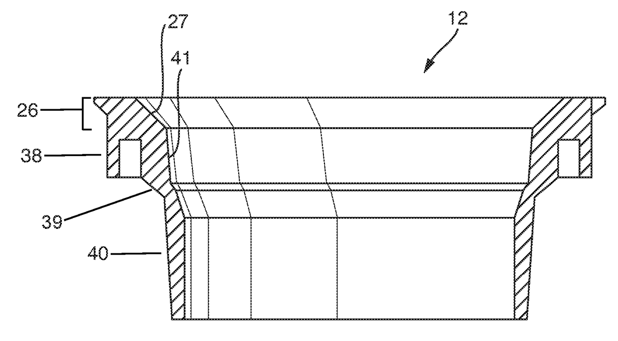
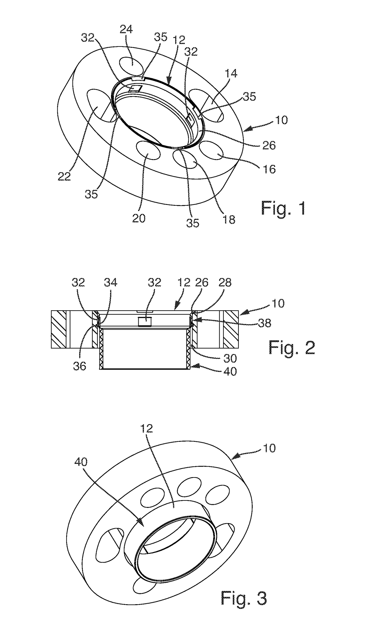
[0040]FIG. 1 illustrates a track widening disc 10 having a centering ring 12 of the track widening system according to the invention. The track widening disc 10 is illustrated has having a total of six wheel bolt holes 14, 16, 18, 20, 22 and 24, however it is to ...


PUM

PropertyMeasurementUnit
diameteraaaaaaaaaa
diameteraaaaaaaaaa
diameteraaaaaaaaaa

Abstract

A track widening system for motor vehicles, having at least one track widening disc and at least one centering ring, which is inserted into a central opening of the track widening disc, wherein the centering ring has at least one catch device which is arranged at the free end of a resilient arm and wherein the track widening disc has at least one corresponding catch device. The centering ring may be plastic, and may be fiber-reinforced. One or more centering rings may have different colors.

Description

CROSS-REFERENCE TO RELATED APPLICATIONS[0001]The present application claims the benefit of priority of German Application No. 10 20140215 986.5, filed Aug. 12, 2014, and of German Application No. 20 2015 000 487.3, filed Jan. 19, 2015, each of which are incorporated herein by reference in their entirety.BACKGROUND[0002]The invention relates to a track widening system or wheel spacer system for motor vehicles. More particularly, embodiments of the present invention pertain to systems having at least one track widening disc or wheel spacer disc and at least one centering ring for insertion into the track widening disc. There heretofore lacks a universal system enabling track widening of differing amounts and centering on wheels having different diameters.BRIEF SUMMARY OF THE INVENTION[0003]An object of the invention is to provide a track widening system for motor vehicles which can be used in a flexible manner for different wheels and different vehicles.[0004]To this end, there is pro...

Claims


Application Information

Patent Timeline
Patent Type & Authority Patents(United States)
IPC IPC(8): B60B3/14B60B19/00B60B3/16
CPCB60B3/147B60B3/16B60B19/00B60B2310/306B60B2360/32B60Y2200/11B60B2900/112B60B2900/116B60B2900/351B60Y2200/10B60B2360/341
Inventor WOHLFARTH, KLAUSWEIDNER, ANDREASSIMONJAN, EDGAR
Owner WOHLFARTH KLAUS
Why Eureka
Try Eureka