Longitudinal control arm

a technology of longitudinal control arm and longitudinal control arm, which is applied in the direction of pivoted suspension arm, vehicle components, and resilient suspensions, etc., can solve the problems of limiting the space conditions below the vehicle, affecting reducing the optimum connection between the longitudinal control arm and the axle tube, so as to achieve flexible design of the longitudinal control arm. , the effect of different widths

Active Publication Date: 2017-05-30
SAF HOLLAND GMBH
View PDF26 Cites 3 Cited by
  • Summary
  • Abstract
  • Description
  • Claims
  • Application Information

AI Technical Summary

Benefits of technology

[0005]Preferably, the longitudinal control arm is formed as a hollow profile at least in regions, wherein the hollow profile preferably has a cross-section, which increases in the direction of the arrangement section on the frame side at least in regions. Preferably, the hollow profile is a box section welded together from individual parts. Particularly preferably, the hollow profile is however made by means of an internal high pressure forming process. Advantageously, the cross-section of the hollow profile increases at least in regions in the direction of the arrangement section on the frame side. Preferably, thus a very rigid design of the arrangement section on the frame side is possible. The longitudinal control arm is advantageously formed such that it has a dirt-repellent design with no undercuts, formation of hollows and recesses etc., making it possible to prevent a damaging accumulation of dirt in the form of stones, dust and saltwater. A further advantage of a transition-less and closed shape of a longitudinal control arm is a low-resistance, streamlined design, which counteracts extreme air turbulence below the vehicle. Preferably, by means of the internal high pressure forming process, the wall thickness may be adapted flexibly to the expected load on the longitudinal control arm. Also preferably, the longitudinal control arm may also be designed as a lattice. Also by using a lattice structure, an optimum orientation based on the forces applied is made possible. It is very advantageous to combine such a lattice structure with the offset between the centerlines of the arrangement sections on the frame side and on the axle tube side. In combination, thus, a very light, rigid and highly flexible design of the longitudinal control arm is made possible. In addition, the combination of the offset with a longitudinal control arm manufactured by means of an internal high pressure forming process is particularly preferred.
[0012]Expediently, the at least one projection connects the longitudinal control arm and the axle tube and / or the wrap in an arc. Advantageously, here, the arc extends substantially transverse to the longitudinal direction from the longitudinal control arm to the axle tube. The arc may be concave or convex. Advantageously, it is designed such that a force flow between the axle tube and the longitudinal control arm may be optimized. To put it differently, the arc represents a connection between the two line contacts so to say. The arc allows for a very stiff attachment of the axle tube. In addition, due to the projection, it is possible to increase so to say the width of the arrangement section on the axle tube side. The load peaks on the axle tube decrease. Furthermore, the force flow between the longitudinal control arm and the axle tube is reduced since the projection provides an additional “force path” by means of the line contact. It should be noted that it would also be possible that the connection between the longitudinal control arm and the axle tube is also exclusively possible by means of the projection(s), i.e. that the original or actual arrangement section on the axle tube side of the longitudinal control arm does no longer have a direct contact with the axle tube. Advantageously, the longitudinal control arm and the axle tube are welded together along the projection at least in regions. As a matter of course, the projection may also be welded to the wrap.
[0013]Expediently, at either side of the arrangement section on the axle tube side a projection is arranged, wherein the two projections preferably have different widths. The width is measured substantially transverse to the longitudinal direction and along the axle tube. Advantageously, by using projections of different widths, the offset of the centerline of the arrangement section on the frame side from the centerline of the arrangement section on the axle tube side may be varied further. Advantageously, this allows for an even more flexible design of the longitudinal control arm. The projection advantageously has a (maximum) height transverse to the longitudinal direction and to the width of the projection. Expediently, there is a height / width relationship of the projection in a range of about 0.2 to 1.8, preferably of about 0.7 to 1.8, and most preferably of about 0.8 to 1.2.

Problems solved by technology

A disadvantage of the known longitudinal control arms, however, is that they are very large and heavy to build since it is required to transmit great forces.
This additionally restricts the limited space conditions below the vehicle or below the vehicle frame.
An optimum connection between the longitudinal control arm and the axle tube or between the longitudinal control arms and the vehicle frame is thus often not possible.
Additionally, there are in most cases limitations on the use of wide-base tires, large drum brakes or also large disk brakes since the known longitudinal control arms build too wide.

Method used


Image

  • Longitudinal control arm
  • Longitudinal control arm
  • Longitudinal control arm

Examples


Embodiment Construction

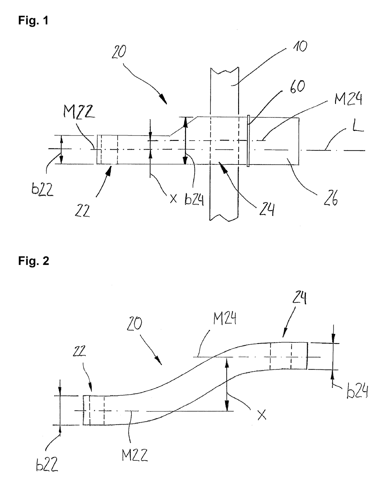
[0024]FIG. 1 shows a schematic representation of a longitudinal control arm 20 in a top plan view (onto a road surface). The longitudinal control arm 20 has an arrangement section 22 on the frame side and an arrangement section 24 on the axle tube side along a longitudinal axis L. A centerline M22 of the arrangement section on the frame side is displaced by an offset x from a centerline M24 of the arrangement section on the axle tube side. Within the arrangement section 24 on the axle tube side, an axle tube 10 is arranged. A width b22 of the arrangement section 22 on the frame side is considerably narrower than a width b24 of the arrangement section 24 on the axle tube side. This difference leads after all to the offset x. The longitudinal control arm 20 is connected to a bearing surface 26 by means of an adapter plate 60.

[0025]FIG. 2 shows a schematic representation of a preferred embodiment of a longitudinal control arm 20 in a top plan view. An arrangement section 22 on the fram...


PUM


Abstract

The invention relates to a longitudinal control arm for connection of an axle tube to a vehicle frame, the longitudinal control arm extending along a longitudinal direction and comprising an arrangement section on a frame side and at least one arrangement section on an axle tube side, a centerline of the arrangement section on the axle tube side being offset by an offset from a centerline of the arrangement section on the frame side when seen at an angle to the longitudinal direction.

Description

BACKGROUND OF THE INVENTION[0001]The present invention relates to a longitudinal control arm for connecting an axle tube to a vehicle frame, as well as a vehicle axle system, in particular for a utility vehicle.[0002]Longitudinal control arms of the type in question are known in the prior art. They are used e.g. in rigid axle systems or steering axle systems of utility vehicles. They serve for connecting an axle tube to a vehicle or to a vehicle frame and ensure that the axle tube is guided laterally. In addition, they form part of the spring and damping system of the chassis, and as such they exhibit respective possibilities of connection for spring and damper elements. A disadvantage of the known longitudinal control arms, however, is that they are very large and heavy to build since it is required to transmit great forces. This additionally restricts the limited space conditions below the vehicle or below the vehicle frame. An optimum connection between the longitudinal control a...

Claims


Application Information

Patent Timeline
Patent Type & Authority Patents(United States)
IPC IPC(8): B60G7/02B60G9/02B60G9/00B60G7/00
CPCB60G7/001B60G7/008B60G7/02B60G9/003B60G9/02B60G2200/31B60G2204/143B60G2204/148B60G2206/012B60G2206/10B60G2206/8201
Inventor SPIELMANN, ROLFHOPPE, MATTHIAS
Owner SAF HOLLAND GMBH
Why Eureka
Try Eureka