
Longitudinal Control Arm

a technology of longitudinal control arm and longitudinal control arm, which is applied in the direction of pivoted suspension arm, vehicle components, and resilient suspensions, etc., can solve the problems of limiting the space conditions below the vehicle, affecting reducing the optimum connection between the longitudinal control arm and the axle tube, so as to achieve flexible design of the longitudinal control arm. , the effect of different widths

Active Publication Date: 2016-06-02
SAF HOLLAND GMBH
View PDF13 Cites 3 Cited by
  • Summary
  • Abstract
  • Description
  • Claims
  • Application Information

AI Technical Summary

Benefits of technology

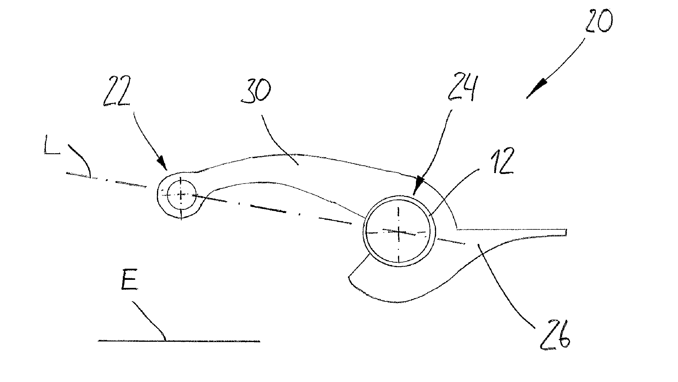
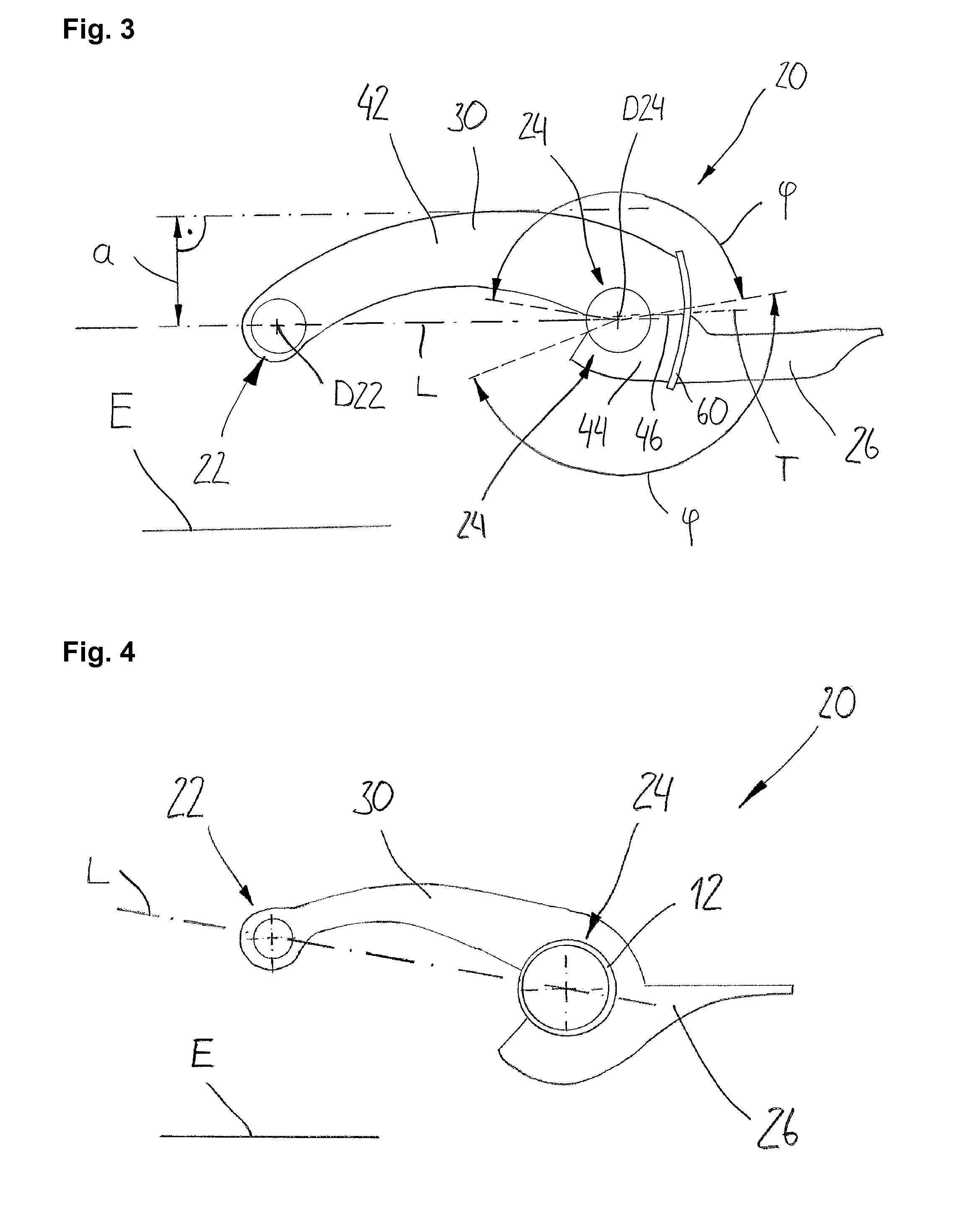
The patent describes a design for a longitudinal control arm used in vehicles. The arm has a hollow profile with a cross-section that increases in the direction of the arrangement section on the frame side. This design allows for a rigid arrangement section on the frame side and a low-resistance, streamlined design at the axle tube. The arm is also designed to prevent the accumulation of dirt and has an optimized orientation based on the forces applied. The arm can be combined with an offset between the centerlines of the arrangement sections on the frame side and on the axle tube side. The use of projections allows for a stiff attachment of the axle tube and reduces the force flow between the arm and the axle tube. The projections can have different widths to further vary the offset of the arrangement section on the frame side. The technical effects of this design include a more flexible design, improved load peaks on the axle tube, and a low-resistance, streamlined design.

Problems solved by technology

A disadvantage of the known longitudinal control arms, however, is that they are very large and heavy to build since it is required to transmit great forces.
This additionally restricts the limited space conditions below the vehicle or below the vehicle frame.
An optimum connection between the longitudinal control arm and the axle tube or between the longitudinal control arms and the vehicle frame is thus often not possible.
Additionally, there are in most cases limitations on the use of wide-base tires, large drum brakes or also large disk brakes since the known longitudinal control arms build too wide.

Method used


Image

  • Longitudinal Control Arm
  • Longitudinal Control Arm
  • Longitudinal Control Arm

Examples


Embodiment Construction

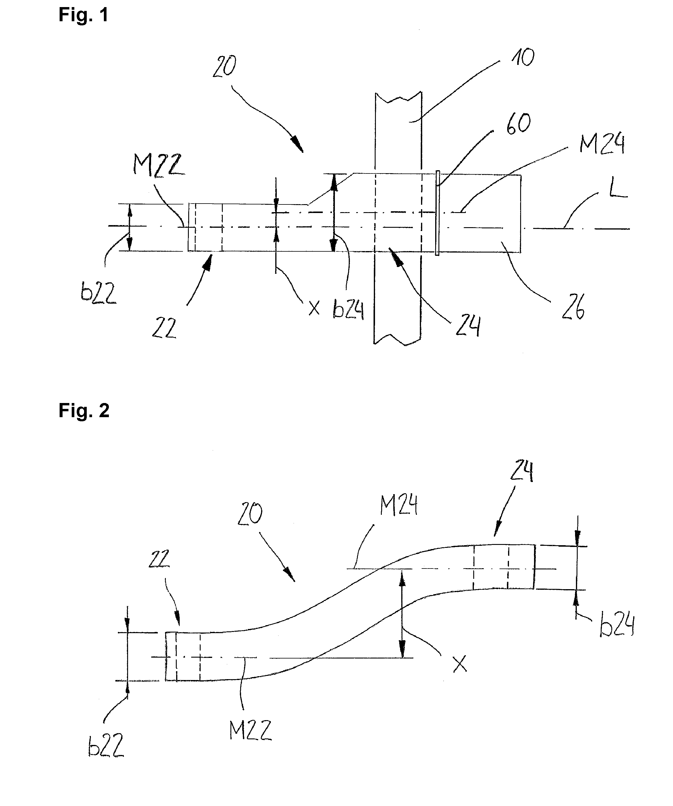
[0024]FIG. 1 shows a schematic representation of a longitudinal control arm 20 in a top plan view (onto a road surface). The longitudinal control arm 20 has an arrangement section 22 on the frame side and an arrangement section 24 on the axle tube side along a longitudinal axis L. A centerline M22 of the arrangement section on the frame side is displaced by an offset x from a centerline M24 of the arrangement section on the axle tube side. Within the arrangement section 24 on the axle tube side, an axle tube 10 is arranged. A width b22 of the arrangement section 22 on the frame side is considerably wider than a width b24 of the arrangement section 24 on the axle tube side. This difference leads after all to the offset x. The longitudinal control arm 20 is connected to a bearing surface 26 by means of an adapter plate 60.

[0025]FIG. 2 shows a schematic representation of a preferred embodiment of a longitudinal control arm 20 in a top plan view. An arrangement section 22 on the frame s...


PUM


Abstract

The invention relates to a longitudinal control arm for connection of an axle tube to a vehicle frame, the longitudinal control arm extending along a longitudinal direction and comprising an arrangement section on a frame side and at least one arrangement section on an axle tube side, a centerline of the arrangement section on the axle tube side being offset by an offset from a centerline of the arrangement section on the frame side when seen at an angle to the longitudinal direction.

Description

BACKGROUND OF THE INVENTION[0001]The present invention relates to a longitudinal control arm for connecting an axle tube to a vehicle frame, as well as a vehicle axle system, in particular for a utility vehicle.[0002]Longitudinal control arms of the type in question are known in the prior art. They are used e.g. in rigid axle systems or steering axle systems of utility vehicles. They serve for connecting an axle tube to a vehicle or to a vehicle frame and ensure that the axle tube is guided laterally. In addition, they form part of the spring and damping system of the chassis, and as such they exhibit respective possibilities of connection for spring and damper elements. A disadvantage of the known longitudinal control arms, however, is that they are very large and heavy to build since it is required to transmit great forces. This additionally restricts the limited space conditions below the vehicle or below the vehicle frame. An optimum connection between the longitudinal control a...

Claims


Application Information

Patent Timeline
IPC IPC(8): B60G7/00B60G9/02
CPCB60G9/02B60G7/001B60G7/008B60G7/02B60G9/003B60G2200/31B60G2204/143B60G2204/148B60G2206/012B60G2206/10B60G2206/8201
Inventor SPIELMANN, ROLFHOPPE, MATTHIAS
Owner SAF HOLLAND GMBH
Learn More