
Seal cap for container closure

a container and sealing technology, applied in the direction of caps, liquid handling, locking devices, etc., can solve the problems of destroying the predetermined breaking element between the edge apron of the seal cap and the cover disc, and the perception of two motions in the opposite direction in the opening motion is very complex in practice, so as to simplify the removal of the seal cap from the container closure

Active Publication Date: 2018-10-02
SCHUETZ GMBH & CO KGAA
View PDF14 Cites 3 Cited by
  • Summary
  • Abstract
  • Description
  • Claims
  • Application Information

AI Technical Summary

Benefits of technology

This design simplifies the removal process by enabling the cap to be removed with a single-direction motion, reducing the necessary pulling force and making the process more intuitive and efficient.

Problems solved by technology

Additionally, the predetermined breaking element between the edge apron of the seal cap and the cover disc is destroyed.
The opening motion composed of two motions in opposite directions is perceived to be very complex in practice, in particular in situations in which relatively limited spatial conditions are present for performing a corresponding opening or removing motion of the seal cap.

Method used


Image

  • Seal cap for container closure
  • Seal cap for container closure
  • Seal cap for container closure

Examples


Embodiment Construction

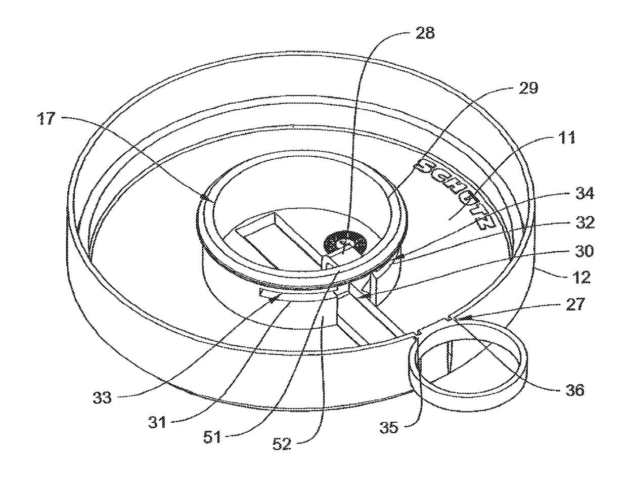
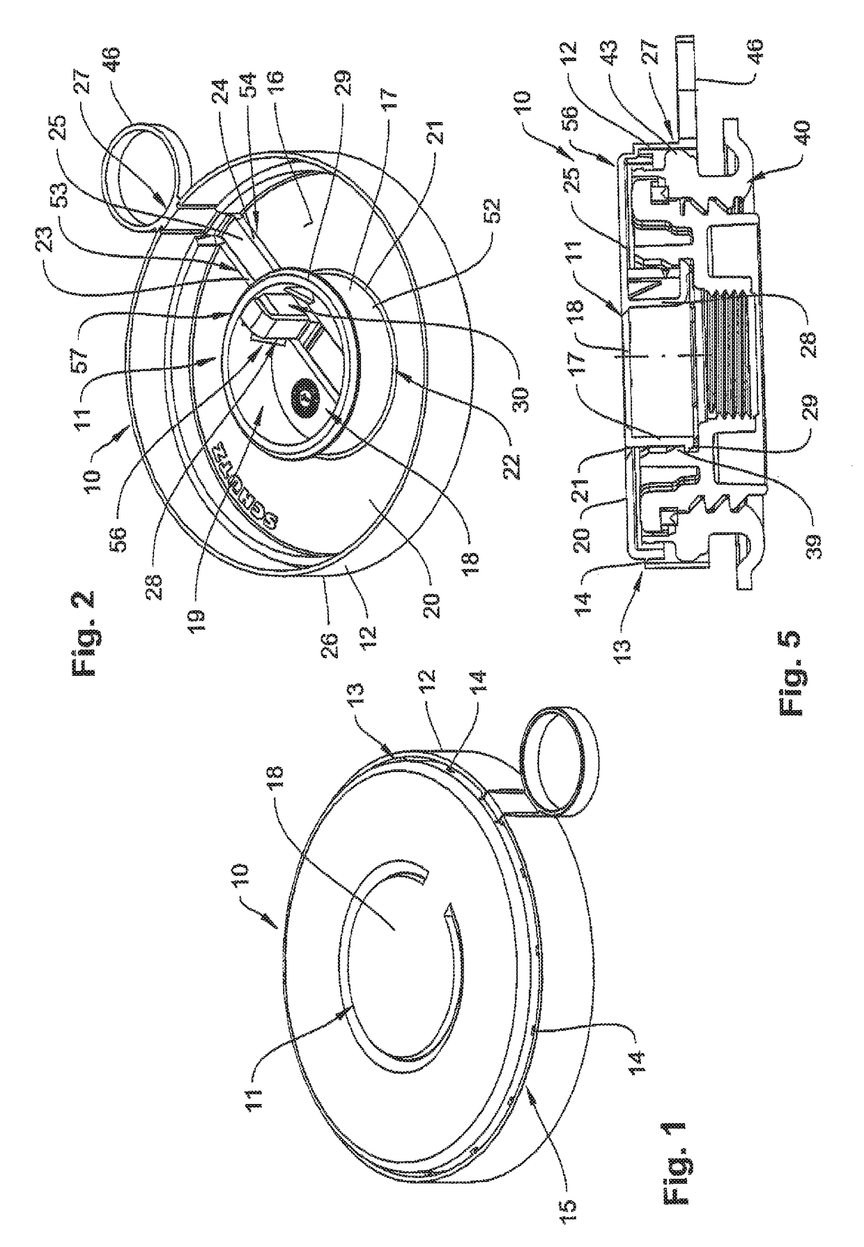
[0037]In FIGS. 1 and 2, a seal cap 10 is illustrated, which has a cover disc 11 and a sleeve-shaped edge apron 12 extending substantially vertically to the cover disc 11 and being connected to the cover disc 11 along an edge-apron predetermined breaking line 13 via predetermined breaking webs 14, which together form a predetermined breaking element 15.

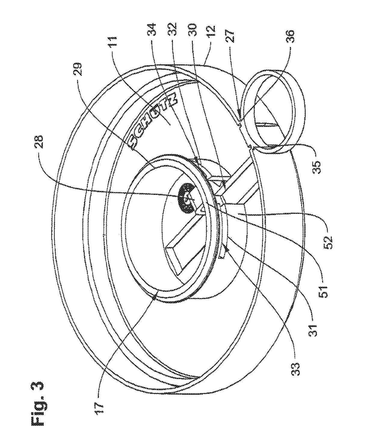
[0038]As can be taken in particular from FIG. 2, a fastening ring 17 is formed on an underside 16 of the cover disc 11, said fastening ring 17 forming a cup portion 19 of the seal cap 10 together with the central inner portion 18 of the cover disc 11 in such a manner that the central inner portion 18 forms a cup bottom of the cup portion 19, said cup bottom being formed integrally in the cover disc. As can further be taken from FIG. 2, the inner portion 18 of the cover disc 11 is separated from an outer portion 20 of the cover disc 11 by a circular inner-portion predetermined breaking line 21, along which a predetermined breaking eleme...


PUM


Abstract

A seal cap (10) for a container closure includes a cover disc (11) having a fastening ring, connected to an underside of the cover disc, with a latching element, for producing a detachable engagement connection with the container closure, connected to a pull tab arranged at the circumference of the cover disc via a connecting element. The connecting element has a cover strip formed in the cover disc that is separated from adjacent areas of the cover disc by lateral cover-strip predetermined breaking lines, which have predetermined breaking elements and has a pull web connected to the latching element of the fastening ring. The cover strip extends from the pull tab, at the circumference of the cover disc into a central inner portion (18) of the cover disc within the fastening ring and the pull web is arranged in an intersecting area between the cover strip and the fastening ring.

Description

CROSS REFERENCE TO RELATED APPLICATIONS[0001]This application is a United States National Phase Application of International Application PCT / DE2014 / 200468 filed Sep. 11, 2014 and claims the benefit of priority under 35 U.S.C. § 119 of German Patent Application 10 2013 221 976.8 filed Oct. 29, 2013 the entire contents of which are incorporated herein by reference.FIELD OF THE INVENTION[0002]The present invention relates to a seal cap for a container closure, comprising a cover disc having a fastening ring connected to an underside of the cover disc, the fastening ring having a latching element for producing a detachable engagement connection with the container closure, the latching element being connected to a pull tab arranged at a circumference of the cover disc via a connecting element, the connecting element having a cover strip formed in the cover disc and separated from adjacent areas of the cover disc by lateral predetermined breaking lines and having a pull web connected to t...

Claims


Application Information

Patent Timeline
Patent Type & Authority Patents(United States)
IPC IPC(8): B65D51/18B65D39/02B65D39/08B65D41/58B65D55/08
CPCB65D51/18B65D39/025B65D39/082B65D55/0863B65D41/58B65D2251/0075B65D2101/0023B65D2251/0015B65D41/32B65D2401/15
Inventor KLATT, BERND
Owner SCHUETZ GMBH & CO KGAA
Learn More