Active phased array antenna system with hierarchical modularized architecture

a phased array antenna and hierarchical technology, applied in antennas, individual energised antenna arrays, electrical devices, etc., can solve the problems of increased manufacturing cost, unfavorable customer service, and inconvenient system architecture, and achieve the effect of simplifying the lines of control signals for rear-end circuit modules

Active Publication Date: 2018-10-02
NAT CHUNG SHAN INST SCI & TECH
View PDF3 Cites 4 Cited by
  • Summary
  • Abstract
  • Description
  • Claims
  • Application Information

AI Technical Summary

Benefits of technology

[0005]Accordingly, an object of the invention is to provide an array antenna system, so that lines of control signals for rear-end circuit modules can be simplified.

Problems solved by technology

It is noted that the conventional system architecture, in which each antenna is connected to a corresponding transmitting / receiving module and phase shifter, is not cost-effective.
Such great numbers of control signal lines and control modules not only cause a greater manufacturing cost, but also increase the circuit board real estate.
In addition, excessive control signal lines and control modules may also lead to cross-interference between signals, energy loss, and increase difficulty of minimizing manufacturing process.
On the other hand, if the period of a periodic array antenna is overly large, grating lobes will be produced; the grating lobes may consume the energy of the main lobe, and thus degrading the performance of the array antenna, which is the difficulty that frequently occurs in design of array antennas.

Method used


Image

  • Active phased array antenna system with hierarchical modularized architecture
  • Active phased array antenna system with hierarchical modularized architecture
  • Active phased array antenna system with hierarchical modularized architecture

Examples


Embodiment Construction

[0022]To make it easier for understanding of the object, aspects, and effects according to this invention, embodiments are provided together with the attached drawings for the detailed description of the invention.

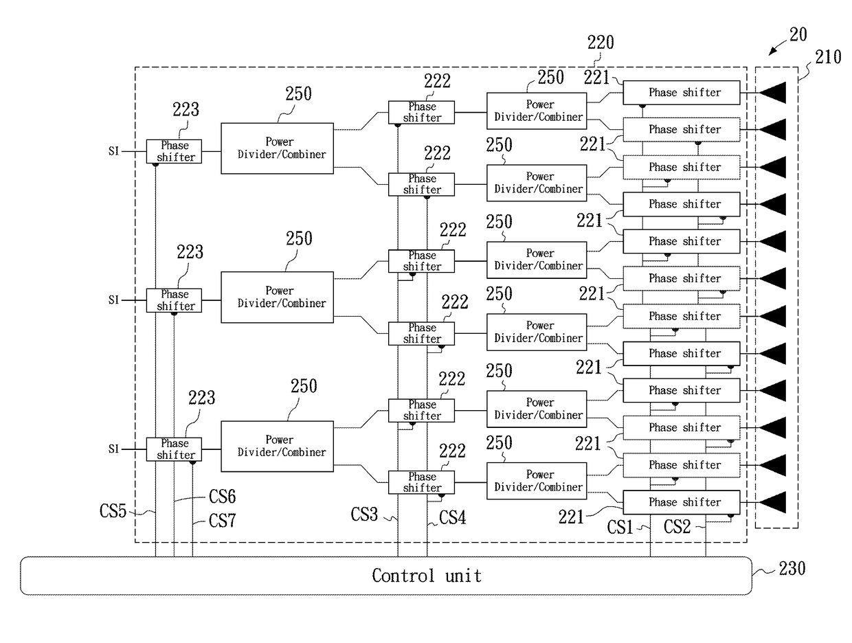
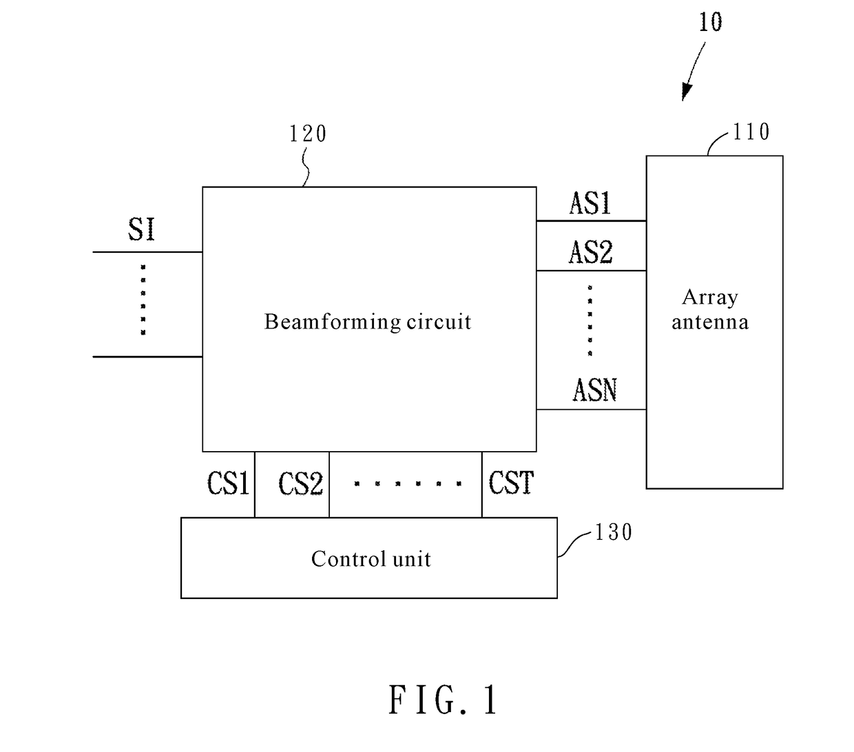
[0023]FIG. 1 is a schematic diagram illustrating the architecture of an active phased array antenna system with hierarchical modularized architecture (hereinafter, an array antenna system) according to an embodiment of the invention. As shown in FIG. 1, an array antenna system 10 comprises: an array antenna 110 and a beamforming circuit 120. The array antenna 110 includes a plurality of antenna units, number of which is N and which are arranged in array form. The beamforming circuit 120 is used for receiving or being coupled to a plurality of input signal SI, and a plurality of phase control signals CS1-CST, wherein the phase control signals each can be indicated by a digital serial signal or digital parallel signals. The beamforming circuit 120 includes: a hierarchical ci...


PUM


Abstract

An active phased array antenna system with hierarchical modularized architecture is introduced, which includes an array antenna and a beamforming circuit. The array antenna includes a plurality of antenna units, number of which is N and which are arranged in array form. The beamforming circuit is for receiving a plurality of input signals and a plurality of phase control signals, and includes a hierarchical circuit structure based on phase shifters, for outputting a plurality of output signals based on the input signals according to phase values corresponding to the phase control signals and combinations of the phase values; the output signals are respectively coupled to the antenna units so as to generate a radiation pattern, wherein number of the phase control signals is T, T<N, wherein N=Πi=1PNi, M=Σi=1PNi, M−P≤T≤M, Ni (i=1 to P), M, P are all positive integers, P≥2, Ni≥2.

Description

FIELD OF THE INVENTION[0001]The present invention relates to is related to an array antenna system, and in particular to an active phased array antenna system with hierarchical modularized architecture.BACKGROUND OF THE INVENTION[0002]In the architecture of signal processing systems, the rear end of each antenna is connected to a corresponding transmitting / receiving module and phase shifter, wherein the transmitting / receiving module includes radio frequency components such as a low noise amplifier (LNA), a power amplifier (PA) and a power attenuator. The transmitting / receiving module is used for providing power, and the array antenna and the phase shifters are for beamforming, wherein it is important that the system cost can be reduced by the reduction in the number of the transmitting / receiving modules and phase shifters.[0003]It is noted that the conventional system architecture, in which each antenna is connected to a corresponding transmitting / receiving module and phase shifter,...

Claims


Application Information

Patent Timeline
Patent Type & Authority Patents(United States)
IPC IPC(8): H01Q21/22H01Q3/26
CPCH01Q3/26H01Q21/22H01Q3/385
Inventor CHOU, HSI-TSENGHUANG, HAO-JUYU, CHIEN-TE
Owner NAT CHUNG SHAN INST SCI & TECH
Why Eureka
Try Eureka