Assembly for LSI test and method for the test

a technology of lsi and test equipment, applied in the field of large-scale integration testing methods and apparatus, can solve the problems of increased test cost, difficulty in testing, and general lsi testers being unable to perform functional tests on target lsi, so as to improve test quality, high functionality, and reduce test cost

Inactive Publication Date: 2007-07-31
SOCIONEXT INC
View PDF22 Cites 1 Cited by
  • Summary
  • Abstract
  • Description
  • Claims
  • Application Information

AI Technical Summary

Benefits of technology

[0012]It is therefore an object of the present invention to provide an assembly for performing a functional test on an LSI in the actual operation at low cost and a method for the test.
[0014]With this unit, it is sufficient for the LSI tester to output simple control signals such as a synchronizing signal and a reset signal as well as test data, as test signals. Accordingly, it is possible to test the function of an LSI in the actual operation using a general LSI tester which does not operate at high speed and is not provided with high functionality. As a result, the cost of the test can be reduced and the quality of the test can be improved.

Problems solved by technology

A general LSI tester, however, cannot perform a functional test on a target LSI by simultaneously supplying a given signal and a signal having a frequency which is not an integral multiple of the given signal to the target LSI.
Therefore, the load board 900 can easily perform a functional test on a simple LSI in the actual operation but has a difficulty in performing the test on a system LSI (system-on-a-chip) having features of high speed, asynchronous and multiple clocks, in the actual operation.
The functional test on a system LSI in the actual operation requires not a general LSI tester but a high-speed and high-performance LSI tester, thus arising a problem of increased cost for the test.
However, when the functional circuit structure of the LSI itself becomes complicated, the number of critical paths increases in the actual operation.
The SCAN test is not effective for detection of such critical paths.
As well known in the art, a structural test such as the SCAN test and a functional test in the actual operation often have different results of failure detection.
The functional test in the actual operation is necessary, but it requires a high-speed and high-functional LSI tester as described above, thus resulting in increased cost for the test.

Method used


Image

  • Assembly for LSI test and method for the test
  • Assembly for LSI test and method for the test
  • Assembly for LSI test and method for the test

Examples


embodiment 1

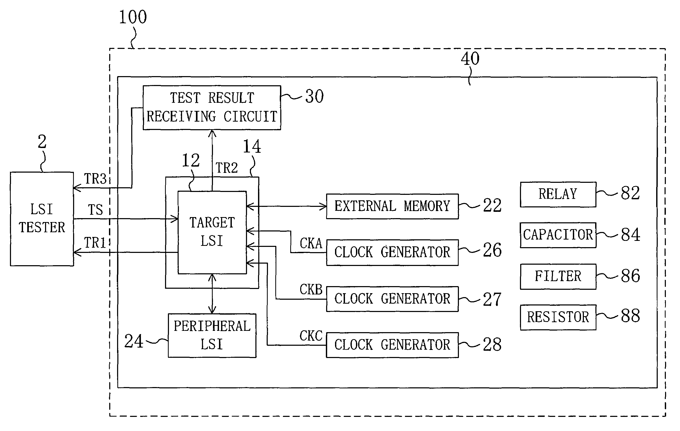
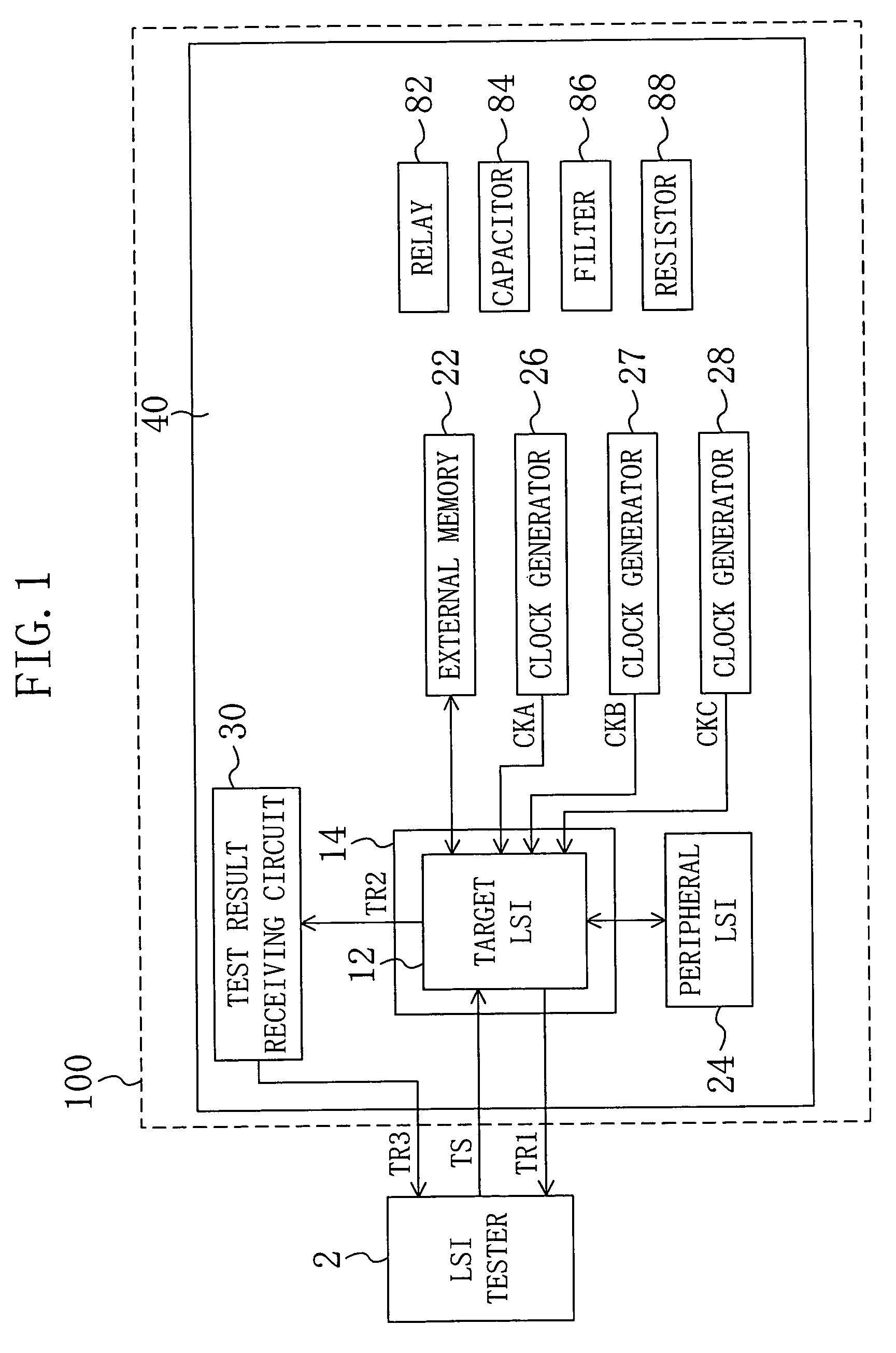
[0026]FIG. 1 is a block diagram showing an example of a configuration of an LSI test system according to a first embodiment of the present invention. The LSI test system shown in FIG. 1 includes: an LSI tester 2; and a load board 100 as an assembly for an LSI test. The load board 100 includes: a socket 14; an external memory 22; a peripheral LSI 24; clock generators 26, 27 and 28; and a test result receiving circuit 30. The load board 100 further includes: a relay 82; a capacitor 84; a filter 86; and a resistor 88, which are passive circuits.

[0027]The load board 100 includes a printed circuit board 40 provided with necessary wiring on which the components described above are mounted. The external memory 22 and the peripheral LSI 24 together constitute a peripheral circuit for a target LSI 12 to be tested.

[0028]The target LSI 12 is inserted into the socket 14 and connected to the other circuits via the socket 14 so that the functional test is performed on the target LSI 12 in the act...

embodiment 2

[0058]In a second embodiment of the present invention, a load board which is easily implemented and is fabricated at reduced cost will be described.

[0059]The load board of the first embodiment is equivalent to a board that uses the target LSI for a set to be actually used by a user with wiring for an LSI test provided on the board. The board for a set actually used by a user or an evaluation board for use in evaluation by the user differ from the load board for use in the LSI test by a LSI vendor in the number of wiring layers and wiring length, so that these boards are fabricated individually in general.

[0060]The fabrications of the respective boards require mutually different techniques and different types of know-how. Accordingly, if the board used by the user and the board used by the LSI vendor are to be combined into one board, these techniques and types of know-how need to be combined, and a highly developed technique is required. However, the user and the LSI vendor are sepa...

embodiment 3

[0069]In a third embodiment of the present invention, an assembly for an LSI test that reduces a cost for the test by transferring data at low speed between an LSI tester and a target LSI to be tested.

[0070]In this embodiment, the case where a target LSI 312 is tested using the load board shown in FIG. 1 will be described. The target LSI 312 has an asynchronous access function of accessing an external memory 22 asynchronously to a clock supplied to the target LSI 312. This allows an LSI tester 2 to access the external memory 22 asynchronously to the clock supplied to the target LSI 312. The load board may be provided with the first and second boards as shown in FIG. 5.

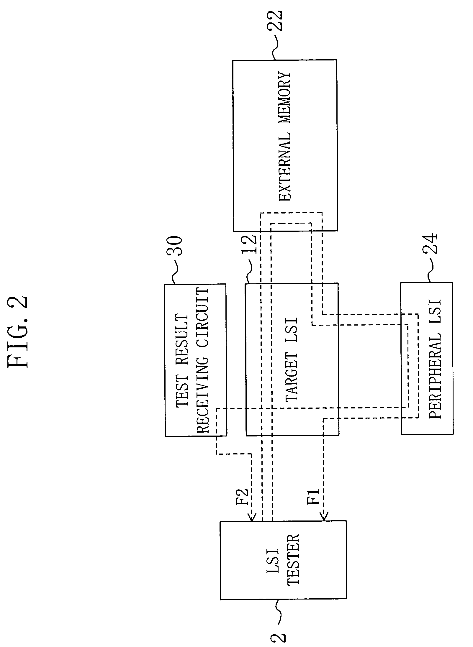
[0071]FIG. 6 is a diagram showing the flow of data in a test according to the third embodiment. First, as indicated by a data flow F31, a test signal TS output from the LSI tester 2 is supplied to the external memory 22 by way of the target LSI 312 and stored in the external memory 22.

[0072]Next, in the same manner as ...


PUM


Abstract

An assembly for an LSI test supplies a test signal output from an LSI tester to a target LSI to be tested and outputs, to the LSI tester, a test result signal generated by processing of the target LSI performed in accordance with the test signal. The assembly for an LSI test includes: a peripheral circuit coupled to the target LSI and allowing the target LSI to operate in the same manner as in the application environment; and a printed circuit board on which the peripheral circuit is mounted.

Description

BACKGROUND OF THE INVENTION[0001]The present invention relates to methods and apparatus for testing large-scale integration (LSI).[0002]LSI tests using LSI testers have been conducted in order to select LSIs that operate normally. The LSI testers test target LSIs independently of other components or in combination with simple components that support the test. The simple components are herein passive elements such as relays, resistors, capacitors and filters.[0003]FIG. 10 is a block diagram showing an example of a configuration of a known LSI test system. The LSI test system shown in FIG. 10 includes an LSI tester 2 and a load board 900. The load board 900 includes a socket 14, a relay 82, a capacitor 84, a filter 86, a resistor 88 and a printed circuit board 940.[0004]A target LSI 912 is inserted into the socket 14 and coupled to the LSI tester 2 via the load board 900 so as to be tested. The relay 82 switches the connection between the target LSI 912 and the LSI tester 2. The capac...

Claims


Application Information

Patent Timeline
Patent Type & Authority Patents(United States)
IPC IPC(8): G01R31/28G01R31/319G01R31/3193
CPCG01R31/31921G01R31/3193G01R31/31935
Inventor ITOH, WATARUKANEMITSU, TOMOHIKOYAMASHITA, TAKERUWATANABE, AKIHIKO
Owner SOCIONEXT INC
Why Eureka
Try Eureka