Light scanning device and method thereof

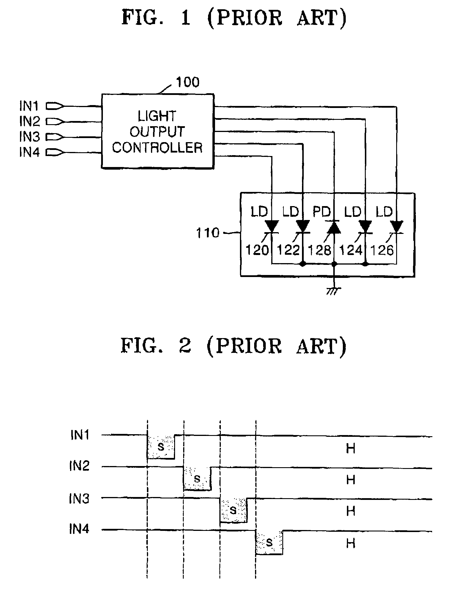
a scanning device and light technology, applied in the direction of pulse manipulation, pulse technique, instruments, etc., can solve the problems of difficult to make a small connector for signal connection, difficult to set a margin for input control time, difficult to standardize an interface, etc., to simplify control signals and compact structur

Inactive Publication Date: 2009-03-03
S PRINTING SOLUTION CO LTD
View PDF13 Cites 1 Cited by
  • Summary
  • Abstract
  • Description
  • Claims
  • Application Information

AI Technical Summary

Benefits of technology

[0015]An aspect of the present invention is to address at least the above problems and / or disadvantages and to provide at least the advantages described below. Accordingly, an aspect of the present invention is to provide a light scanning device and a method thereof capable of allowing for the standardization of an interface by simplifying control signals inputted to the light scanning device and making a more compact structure possible by reducing the size of the signal connector used in the light scanning device for generating a plurality of lights and included in an image-forming apparatus such as a printer or multifunction machine.

Problems solved by technology

Since the conventional quad beam scanning device requires four S&H signal inputs as described above, it is difficult to set a margin for an input control time.
Also, since the related art quad beam scanning device requires a plurality of input signals, it is difficult to standardize an interface and it is difficult to make a small connector for signal connection.
As such, a compact apparatus is difficult to realize.

Method used


Image

  • Light scanning device and method thereof
  • Light scanning device and method thereof
  • Light scanning device and method thereof

Examples


Embodiment Construction

[0030]The matters defined in the description such as a detailed construction and elements are provided to assist in a comprehensive understanding of the embodiments of the invention. Accordingly, those of ordinary skill in the art will recognize that various changes and modifications of the embodiments described herein can be made without departing from the scope and spirit of the invention. Also, descriptions of well-known functions and constructions are omitted for clarity and conciseness. Exemplary embodiments of the present invention will now be described with reference to the accompanying drawings.

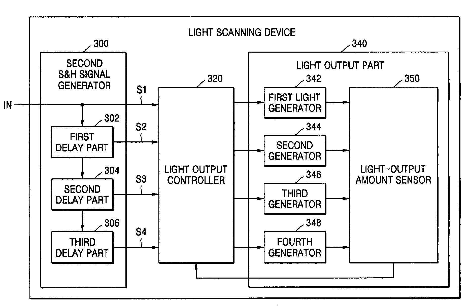
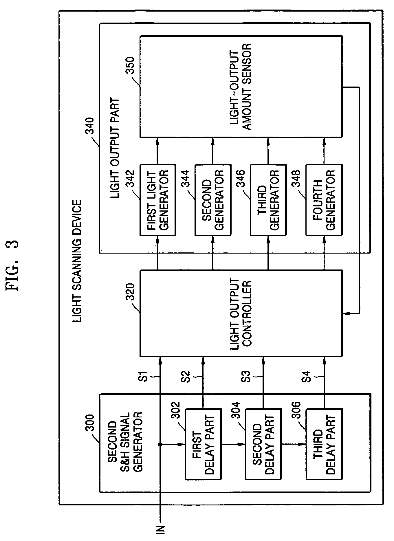
[0031]FIG. 3 is a block diagram of a light scanning device according to an exemplary embodiment of the present invention. The light scanning device includes the second S&H signal generator 300, a light output controller 320, and a light output part 340.

[0032]The second S&H signal generator 300 receives a first S&H signal IN, comprising a sampling interval and a holding interval, from ...


PUM


Abstract

A light scanning device and a method thereof are provided. The device is under control of a controller for controlling an image-forming apparatus and includes a second S&H signal generator, light output part, and a light output controller. The second S&H signal generator generates a plurality of second S&H signals, each consisting of a sampling interval and a holding interval and generated using a first S&H signal provided from the controller. The light output part outputs a plurality of lights and the light output controller controls the light output part to generate the plurality of lights for the respective sampling intervals of the plurality of second S&H signals and sets a control signal value controlling intensities of lights to be maintained for the holding intervals of the plurality of second S&H signals on the basis of the intensities of the generated light. Accordingly, standardization of an interface between parts is simplified.

Description

CROSS-REFERENCE TO RELATED PATENT APPLICATION[0001]This application claims the benefit under 35 U.S.C. § 119(a) of Korean Patent Application No. 10-2005-0063286, filed on Jul. 13, 2005, in the Korean Intellectual Property Office, the entire disclosure of which is hereby incorporated by reference.BACKGROUND OF THE INVENTION[0002]1. Field of the Invention[0003]The present invention relates to a light scanning device and a method thereof. More particularly, the present invention relates to a light scanning device and a method thereof capable of standardizing an interface by simplifying control signals inputted to the light scanning device and reducing the size of a connector for signal connection in an apparatus including the light scanning device, such as a printer or multifunction machine, using a laser beam.[0004]2. Description of the Related Art[0005]An electrophotographic image-forming apparatus performs a printing operation in the following way. First, a light scanning device sca...

Claims


Application Information

Patent Timeline
Patent Type & Authority Patents(United States)
IPC IPC(8): B41J2/435G11C27/02H03M1/00
CPCH04N1/40037H04N1/4005G03G15/04G03G15/0415G03G15/50
Inventor LEE, JONG-MIN
Owner S PRINTING SOLUTION CO LTD
Why Eureka
Try Eureka