Circuit for driving high-power ultrasonic transducer by one square wave

A square-wave drive, high-power technology, applied in the field of circuits, can solve the problems of the single-chip microcomputer program requiring high performance requirements of the single-chip microcomputer itself, and the complicated design of the control circuit of the ultrasonic power supply, so as to achieve high-power ultrasonic signal output, large rated current, good stability

Active Publication Date: 2013-09-18
CONPROFE TECH GRP CO LTD +1
View PDF6 Cites 2 Cited by
  • Summary
  • Abstract
  • Description
  • Claims
  • Application Information

AI Technical Summary

Problems solved by technology

At this stage, the power of ultrasonic transducers in domestic industrial applications is increasing, and the output power of ultrasonic power supplies is required to meet the power requirements of transducers and match them. In general, the control circuit design of ultrasonic power supplies is very complicated. , the requirements for the MCU program and the performance requirements of the MCU are relatively high

Method used


Image

  • Circuit for driving high-power ultrasonic transducer by one square wave

Examples


Embodiment Construction

[0008] The specific implementation manner of the present invention will be further described below in conjunction with the accompanying drawings.

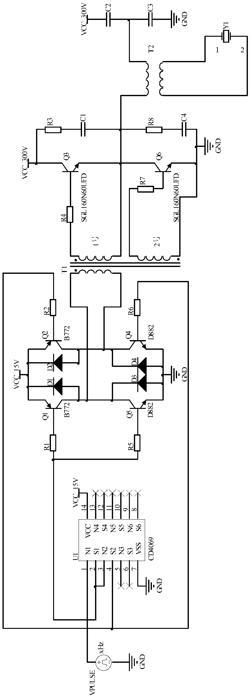
[0009] Such as figure 1 As shown, the circuit for driving a high-power ultrasonic transducer by a square wave includes a pulsed square wave voltage source VPULSE, an inverter U1, a first resistor R1, a second resistor R2, a third resistor R3, a fourth resistor R4, a Fifth resistor R5, sixth resistor R6, seventh resistor R7, eighth resistor R8, first triode Q1, second triode Q2, third triode Q4, fourth triode Q5, first two Diode D1, second diode D2, third diode D3, fourth diode D4, first transformer T1, second transformer T2, first IGBT Q3, second IGBT The polar transistor Q6, the first capacitor C1, the second capacitor C2, the third capacitor C3, the fourth capacitor C4, and the transducer Y1. The signal of the inverter U1 is CD4069.

[0010] One end of the pulsed square wave voltage source VPULSE is grounded, the other end is ...


PUM


Abstract

The invention discloses a circuit for driving a high-power ultrasonic transducer by one square wave. At present, the power of an ultrasonic transducer in the domestic industry becomes higher and higher, so that the output power of an ultrasonic power supply is required to meet a requirement on the power of the transducer and is required to match the power of the transducer; under normal circumstances, a control circuit of an ultrasonic generating power supply is very complex in design and has relatively high requirements on the program and the performance of a singlechip. The circuit for driving the high-power ultrasonic transducer by one square wave comprises a pulse square wave voltage source VPULSE, an inverter, eight resistors, four transistors, four diodes, two transformers, two insulated gate bipolar transistors, four capacitors and a transducer. The components used by the circuit disclosed by the invention are mature, reliable, low in cost and rich in sources; a single-way square wave signal and a control signal can be input simply; a bridge current circuit is high in stability; the transformer ratio of a driving transformer is large; the rated current of the IGBT (insulated gate bipolar translator) is high; high-power ultrasonic signal output can be achieved.

Description

technical field [0001] The invention belongs to the technical field of industrial control and relates to a circuit, in particular to a circuit in which a high-power ultrasonic transducer is driven by one square wave. Background technique [0002] The ultrasonic power supply is also called an ultrasonic generator, and its function is to convert electrical energy into a high-frequency alternating current signal that matches the ultrasonic transducer. At this stage, the power of ultrasonic transducers in domestic industrial applications is increasing, and the output power of ultrasonic power supplies is required to meet the power requirements of transducers and match them. In general, the control circuit design of ultrasonic power supplies is very complicated. , The requirements for the MCU program and the performance requirements of the MCU are relatively high. In view of the above practical problems, the present invention designs a circuit for driving a high-power ultrasonic...

Claims


Application Information

Patent Timeline
Patent Type & Authority Applications(China)
IPC IPC(8): B06B1/02
Inventor 赵晓东李双双孔亚广
Owner CONPROFE TECH GRP CO LTD
Why Eureka
Try Eureka