Implantable medical device with twisted element

a medical device and element technology, applied in the field of implantable medical devices, can solve the problems of loss of instantaneous occlusion and/or risk of leakage through the opening, reduced compressibility, and relatively difficult deployment of devices, and achieve the effect of enhancing the closing

Active Publication Date: 2018-10-09
COOK MEDICAL TECH LLC
View PDF15 Cites 0 Cited by
  • Summary
  • Abstract
  • Description
  • Claims
  • Application Information

AI Technical Summary

Benefits of technology

[0010]The twisting of the sleeve within the tubular support element causes the lumen of the sleeve to be twisted closed, which in practice will therefore close the passage through the device. However, it is still possible to pass an introducer assembly element through the sleeve, in particular a guide wire, enabling the device to be deployed over the wire, thereby benefitting from optimal deployment procedures. The twist of the sleeve will loosen when the device is radially compressed, as it is when held onto a carrier element of an introducer assembly, thereby opening the lumen in the sleeve and facilitating passage of a guide wire, for example, through the device. The twist will tighten when the device is allowed to expand off the carrier element and against the vessel wall, thereby closing the lumen. It is envisaged that the structure could be designed still to accommodate a guide wire, for instance in the sleeve when the device is expanded, so that the guide wire can be removed only after deployment of the device. On removal of the guide wire, blood pressure will impinge on the fabric of the sleeve, pushing this closed. The structure also avoids the risk of recanalization of the vessel. These characteristics are described in detail below.
[0016]Advantageously, the tubular support element has a length, the sleeve having between the first and second ends of the support element a length greater than the length of the support element. The length of sleeve between the first and second ends of the support element may be at least 5 percent greater than the length of the support element, preferably at least 15 percent greater, more preferably least 25 percent greater. The greater length of the sleeve relative to the support element provides a certain looseness of the sleeve in the support, which can enhance the closing effect when blood pressure impinges on the twisted sleeve.

Problems solved by technology

However, these devices can be relatively difficult to deploy, typically not being suitable for delivery over a guide wire.
Leaving any opening in the device for the passage of a guide wire can lead to loss of instantaneous occlusion and / or risk of leakage through the opening.
For instance, a valve to close such an opening can lead to reduced compressibility for delivery purposes and is also liable to open or leak in use, thereby risking loss of occlusion function.
Reliance on the creation of a thrombus to close the aperture, however small, fails to achieve instantaneous closure of the vessel, also is also at risk of recanalization.
However, such devices occlude a vessel only over time, often taking hours.
They can also be liable to recanalization over time.

Method used


Image

  • Implantable medical device with twisted element
  • Implantable medical device with twisted element
  • Implantable medical device with twisted element

Examples


Embodiment Construction

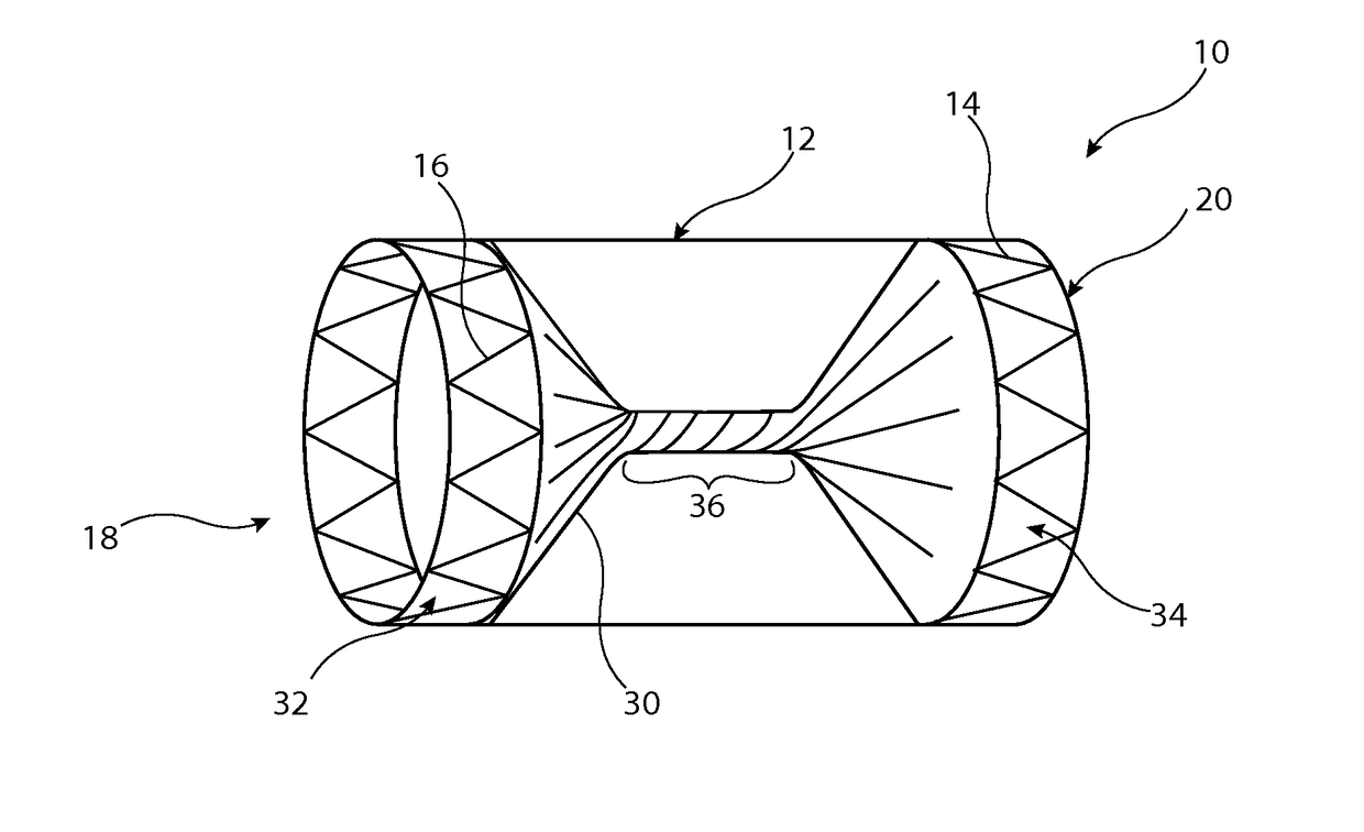
[0028]The preferred embodiment described below is configured as a vascular occluder. It is to be understood, though, that the medical device could be configured to perform other functions, such as a vascular filter.

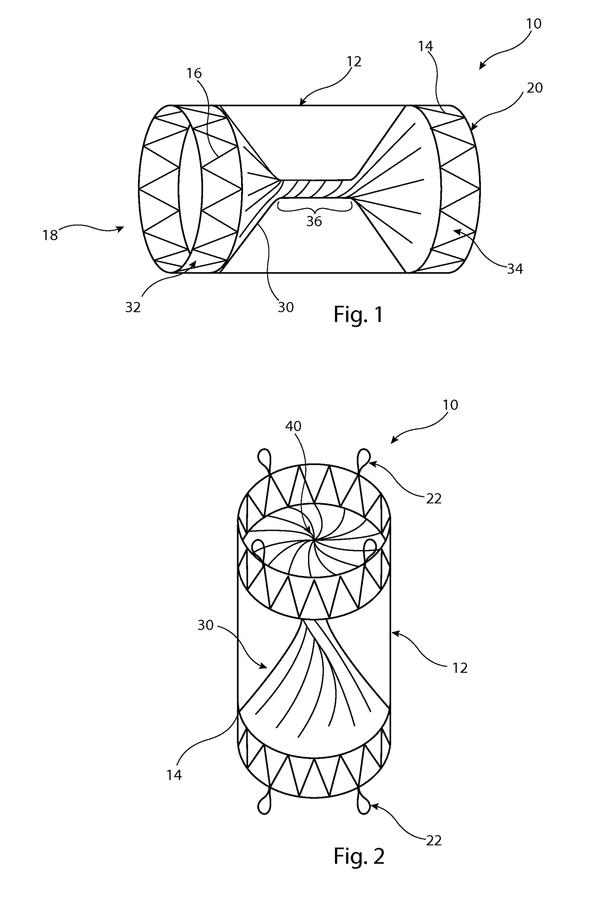
[0029]Referring first to FIG. 1, this shows an implantable medical device 10 in the form, in this embodiment, of a vascular occluder. The device 10 includes a tubular support element 12 which in this embodiment is a stent formed of a plurality of zigzag stent rings 14 coupled together by a series of tie bars 16 connected in this example to apices or troughs of adjacent stent rings 14. The support element 12 is substantially cylindrical and round in transverse cross-section, although in other embodiments could have a different shape, for instance a tapering form or with a central waist. It is to be appreciated that stent rings 14 could extend for the whole length of the tubular support element 12, that is also with stent rings located between the end stents which are shown...


PUM


Abstract

A vascular occluder includes a tubular support element and a sleeve of occluding material disposed within the support element. The sleeve is twisted in the support creating a constriction which closes the lumen of the sleeve. The lumen of the sleeve can nevertheless be opened by a guide wire or cannula for over the wire delivery. Once the guide wire or cannula are withdrawn from the sleeve, the sleeve will close again by the action of blood pressure thereon. Blood pressure will act to maintain closing pressure on the sleeve, thereby avoiding or reducing the risk of recanalization.

Description

RELATED APPLICATIONS[0001]This application claims the benefit of priority under 35 U.S.C. § 119(a) to European Patent Application No. EP 15275101.2, filed Mar. 31, 2015 and Great Britain Patent Application No. GB 1407686.3, filed on May 1, 2014, both of which are incorporated by reference here in their entirety.TECHNICAL FIELD[0002]The present invention relates to an implantable medical device, in particular but not exclusively to a vascular occlusion device. The device could also be configured as a filter.BACKGROUND ART[0003]Vascular occlusion devices are well known in the art and can have many forms. A convenient type of occluder is one which is implanted in the vessel of a patient and is deployable via endoluminal insertion from a remote percutaneous entry point. This type of occlusion device can avoid the need for invasive open surgery, vessel ligation and so on. Some such devices can also be removable from the patient via an endoluminal retrieval procedure once no longer requir...

Claims


Application Information

Patent Timeline
Patent Type & Authority Patents(United States)
IPC IPC(8): A61B17/12A61F2/844A61F2/90A61F2/01
CPCA61B17/12109A61B17/12031A61B17/12131A61B17/12172A61B17/12177A61F2/844A61F2/90A61F2/01A61F2230/001A61F2002/011A61F2002/016A61F2002/018A61F2/011A61B17/12022A61B17/12168
Inventor BODEWADT, TUE THURENHANSEN, CHRISTINA RAUFFJENSEN, KIM MOGELVANGJENSEN, RAIMO URBANRASMUSSEN, ERIK E.
Owner COOK MEDICAL TECH LLC
Why Eureka
Try Eureka