Multi mode wave energy converter with elongated wave front parallel float having integral lower shoaling extension
What is AI technical title?
AI technical title is built by Patsnap AI team. It summarizes the technical point description of the patent document.
a wave front and wave energy converter technology, applied in the field of wave energy converters, can solve the problem of high capital cost (capex)
Active Publication Date: 2018-10-09
ROHRER TECH
View PDF12 Cites 5 Cited by
Summary
Abstract
Description
Claims
Application Information
AI Technical Summary
This helps you quickly interpret patents by identifying the three key elements:
Problems solved by technology
Method used
Benefits of technology
Benefits of technology
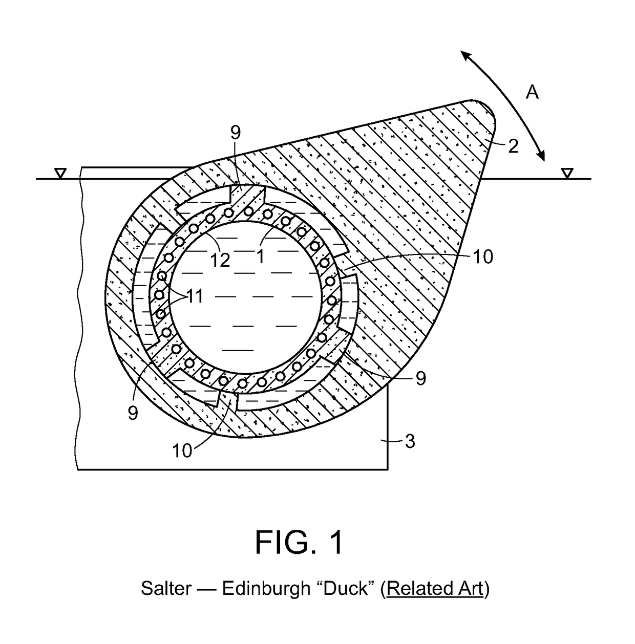
[0016]A primary wave energy capture efficiency advantage of the Salter Duck (and the WEPTOs and StingRay WECs which utilize the Duck float geometry) is the minimal energy consuming “back wave” produced when the protruding forward facing buoyant Duck float lobes rotate upward and rearward in response to oncoming combined wave heave and surge forces and subsequently rotate forward and downward on subsequent wave troughs. The upward and rearward Duck float lobe movement allows concurrent capture of both wave heave and wave surge energy. Most WECs capture a portion of either wave heave or wave surge energy but not both.
[0027]In summary, the present disclosure provides WEC cost (CAPEX) advantages plus improved wave energy capture efficiency, and severe sea survival advantages not available to WECs using Duck like floats with large central cylinders or other WEC types.
Problems solved by technology
Unfortunately, Salter's scaled wave tank experiments found that good wave energy capture efficiency required very large Duck float central cylinder diameters (see prior reference to 1977 Nature article above).
They require a wide (to intercept more wave front) large diameter (6-18 meter) water tight air filled central cylinders (housing their PTO equipment) resulting in high capital cost (CAPEX).
Firstly, a major portion of each oncoming wave's kinetic or surge forces impact the cylinder below its equator deflecting kinetic energy downward rather than upward to lift the lobe or float.
Method used
Image
Click on the blue label to locate the original text in one second.
Reading with bidirectional positioning of images and text.
Examples
Embodiment Construction
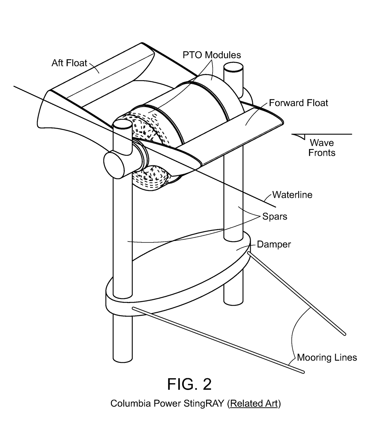
[0041]FIG. 1 and FIG. 2 of the Salter Duck and the Columbia StingRay, respectively, are related prior art and are described in their references cited including GB1482085 (Salter) and US 2015 / 0252777 (Rhinefrank). They are also described and distinguished from the present disclosure in the BACKGROUND OF THE DISCLOSURE and SUMMARY OF THE DISCLOSURE sections above.
[0042]FIG. 3 and FIG. 4 are described in Rohrer U.S. Pat. No. 9,127,640 and Rohrer US 2015 / 0082785, respectively, both of which are incorporated herein by reference and both of which this application is a continuation-in-part. The element numbers used in FIG. 4 and FIG. 5 are consistent with those used to describe the present disclosure.
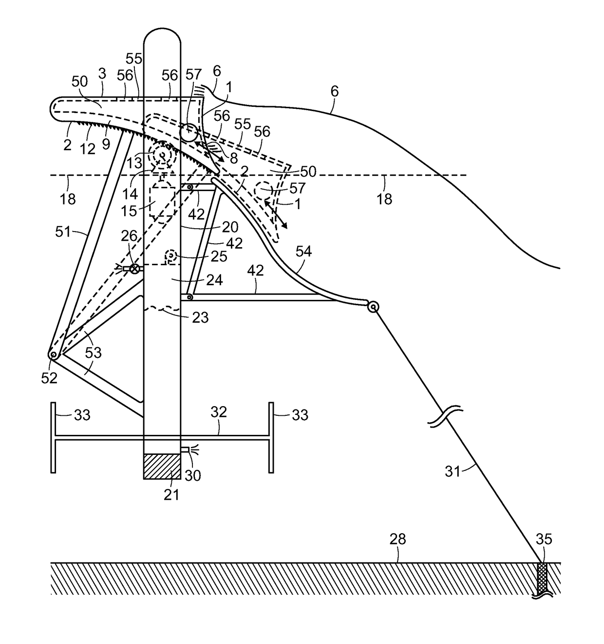
[0043]FIG. 3 describes a float 3 rotatably attached by swing arms 51 to a buoyant vertical spar frame 20 at pivot point or pivot axis 52. The generator 15 is housed within frame column 20 and driven by rack gear 12 on the float bottom through pinion gear 13 on the frame 20. The FIG. 3 embodime...
PUM
Abstract
A wave barrier or wave terminator type ocean wave energy converter (WEC) utilizing one or multiple adjacent floats together forming an elongated wave front parallel (EWFP) float rotatably connected by at least one swing or drive arm to a secondary floating or shore or seabed fixed body or frame, such that the at least one swing arm is rotating about a submerged pivot point or axle on such body or frame and constraining the motion of the float(s) relative to the body or frame when wave forces are applied against the float(s). Relative to the direction of oncoming wave fronts and relative to the still water line (SWL), the at least one EWFP float is substantially forward of, and above, the pivot point such that the float concurrently moves both upward and rearward on wave crests and returns both forward and downward on ensuing wave troughs. The rear surface of the EWFP float is substantially arcuate and concave with a radius approximating its distance from the pivot point such that the float produces minimal energy consuming back waves when it is being moved by oncoming wave forces. The lower rear arcuate surface of the float can extend below the bottom of the float deeper into the water column to capture additional wave energy.
Description
CROSS-REFERENCE TO RELATED APPLICATIONS[0001]This is a Continuation-In Part of U.S. Regular Utility application Ser. No. 14 / 530,723, filed Nov. 1, 2014, which is a Continuation-in-Part of U.S. Regular Utility application Ser. No. 14 / 101,325, filed Dec. 9, 2013, now U.S. Pat. No. 9,127,640, issued Sep. 8, 2015, which is a Continuation-In-Part of U.S. Regular Utility application Ser. No. 13 / 506,680, filed May 8, 2012, now U.S. Pat. No. 8,614,520, issued Dec. 24, 2013, and claims the benefit of U.S. Provisional Application Ser. No. 62 / 284,640 filed Oct. 5, 2015, the contents all of which are incorporated in their entirety herein by reference.FIELD OF THE DISCLOSURE[0002]This disclosure relates to the production of electrical power, pressurized water, or other useful work from surface waves on a water body. More particularly, this disclosure relates to Wave Energy Converters (“WEC”) of the wave terminator or barrier type, wherein one or more elongated buoyant surface floats or bodies, o...
Claims
Application Information
Patent Timeline
Application Date:The date an application was filed.
Publication Date:The date a patent or application was officially published.
First Publication Date:The earliest publication date of a patent with the same application number.
Issue Date:Publication date of the patent grant document.
PCT Entry Date:The Entry date of PCT National Phase.
Estimated Expiry Date:The statutory expiry date of a patent right according to the Patent Law, and it is the longest term of protection that the patent right can achieve without the termination of the patent right due to other reasons(Term extension factor has been taken into account ).
Invalid Date:Actual expiry date is based on effective date or publication date of legal transaction data of invalid patent.

