Glass melting plant

a glass melting plant and glass technology, applied in glass making apparatus, furnace types, charging furnaces, etc., can solve the problems of increasing theoretical energy consumption in particular, affecting the specific melting performance of glass, and reducing the energy required per ton of glass produced, so as to achieve the effect of increasing specific melting performance and maintaining minimal energy consumption

Inactive Publication Date: 2018-11-13
BETEILIGUNGEN SORG
View PDF12 Cites 0 Cited by
  • Summary
  • Abstract
  • Description
  • Claims
  • Application Information

AI Technical Summary

Benefits of technology

[0022]Therefore, the object of the present invention is to fashion a glass melting tank of the type named above in such a way that the specific melting performance is increased with glass quality remaining at least the same, the energy consumption continuing to remain minimal.
[0023]According to the present invention, this object is achieved in that the feeding surface of the doghouse is at least 8 m2 and, given a melt surface greater than or equal to 115 m2, is at least 7% of the melt surface of the melting tank. Advantageously, the feeding surface is at most 25% of the melt surface of the melting tank. At the indicated size of the feeding surface, on the one hand a high specific melting performance is achieved, and on the other hand the melt bath surface is free of the raw material covering to such an extent that energy can enter adequately into the glass melt. This is achieved through the significant enlargement of the doghouse according to the present invention. The radiation into the doghouse permits a conditioned energy input from above onto the charge. Due to the enlarged doghouse, the covering of the melt bath surface in the melting tank is reduced relative to the glass throughput. In this way, adequate free surface is available, making it possible to transport the energy input into the glass melt and, finally, under the batch covering.

Problems solved by technology

Therefore, a great deal of effort is made to reduce the energy required per ton of glass produced.
However, these developments quickly run up against technological limits.
In practice, the theoretical energy consumption increases significantly in particular due to three additional sources of heat loss: heat losses through the walls of the melting plant, heat losses due to the conducting of the hot combustion gases out of the melting plant, and heat losses due to the heat content of the melt flow itself leaving the melting plant towards the processing.
Despite all technological improvements, in the currently existing art a specific energy consumption of more than 4 GJ / t is standard.
This is done through pelleting, a solution that however requires a large outlay and is expensive due to the necessary comminution of the raw materials and thermal treatment.The energy consumption can also be improved to a limited extent by modifying the composition of the components.
Working against this, however, are further technical facts that increase the energy consumption.
Due to the comparatively high viscosity, even at a high process temperature, this outlay is considerable.
This heat exchanger process is however physically limited in its effectiveness.
A correspondingly high cooling power again has the consequence of an unnecessary heat loss.
This further reduces the heat conduction.
However, these technical teachings have a plurality of disadvantages: the direct burner impulse, in contact with the still-unmelted raw material, causes significant formation of dust.
The high energy density, caused by the direct burner contact with the raw materials, can cause significant vaporization of the components with high vapor pressure (for example alkalis).
A significant enlargement of the melting tank, necessary for the application of this principle in order to obtain more surface not covered by batch, is however very expensive technically and financially.

Method used


Image

  • Glass melting plant
  • Glass melting plant
  • Glass melting plant

Examples


Embodiment Construction

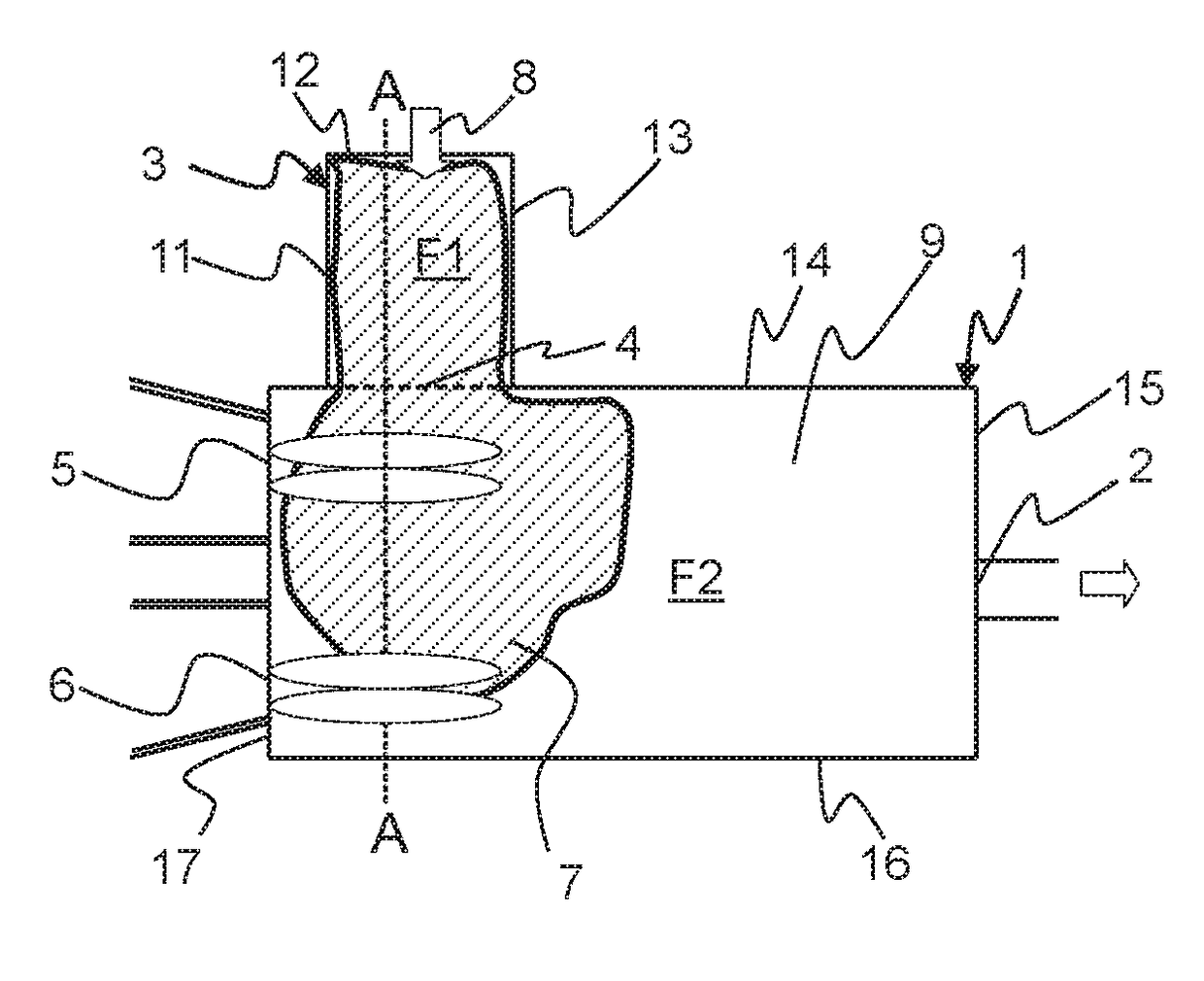
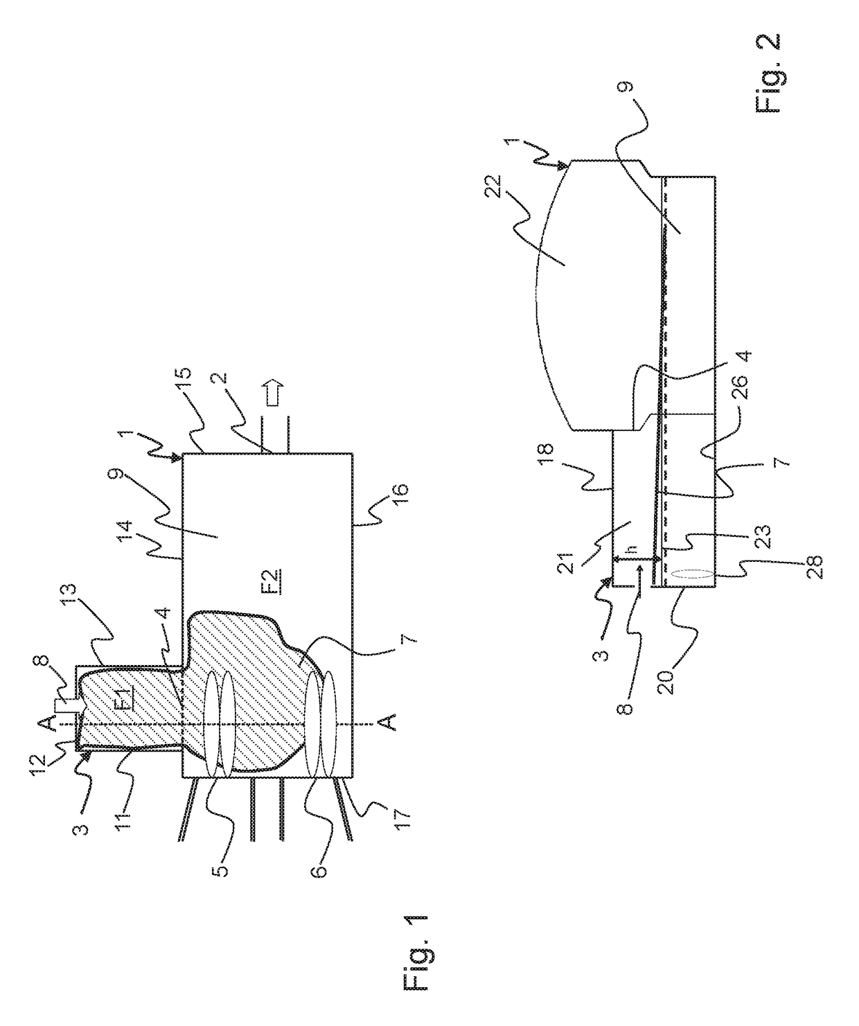
[0048]FIG. 1 shows a melting tank 1 of a glass melting plant (not shown in more detail) of the end-fired type, on whose one side wall 14 there is situated a doghouse 3. The doghouse 3 ends at an inlet 4 of the melting tank 1, and there opens into the melting tank 1. At the left side of FIG. 1, i.e., at a side wall 17 of the melting tank 1, burner ports 5, 6 are indicated of the two burners situated alongside one another, with the supply of the oxidant and of fuel. Connected to these, for regenerative heat recuperation, are two chambers (also not shown) of a regenerator. At a side wall 15, which is situated opposite the side wall 17 with the burner ports 5, 6, there is situated a preferably channel-shaped outlet 2 of melting tank 1, which is used for the removal of the glass melt.

[0049]The glass melting plant is continuously fed with unmelted charge material 7. Here, the charge 7 is supplied to the doghouse 3 via a feeding device (not shown). This is indicated by arrow 8. From there,...


PUM

PropertyMeasurementUnit
melt surface areaaaaaaaaaaa
areaaaaaaaaaaa

Abstract

A glass melting plant having a melting tank having end-fired heating, the melting tank having a feeding material inlet, an outlet for removing the molten glass, and a melt surface of at least 40 m2. At least one doghouse is laterally situated and is connected to the melting tank inlet for feeding material input. The doghouse has side walls that, together with the melting tank inlet, limit a feeding surface area, and has a feeding device. The doghouse has a roof with an end wall oriented toward the feeding device, which end wall encloses, with the roof, a gas compartment open toward the melting tank. To increase the specific melting performance with at least equal glass quality, the feeding surface of the doghouse is at least 8 m2 and, given a melt surface of at least 115 m2, is at least 7% of the melting tank melt surface.

Description

CROSS-REFERENCES TO RELATED APPLICATIONS[0001]This application claims the benefit of the German patent application No. 10 2015 106 455.3 filed on Apr. 27, 2015, and German patent application No. 10 2015 108 195.4 filed on May 22, 2015, the entire disclosures of which are incorporated herein by way of reference.BACKGROUND OF THE INVENTION[0002]The present invention relates to a glass melting plant having a melting tank having end-fired heating, having side walls and a floor, and the melting tank having a melt surface of at least 40 m2. The melting plant is fed from one side, via a doghouse having a feeding device.[0003]The melting tank standardly has an inlet for supplying the feed material charge, a preferably channel-shaped outlet for removing the molten glass, the inlet of the melting tank being connected to the doghouse and the doghouse having a roof that has an end wall facing the feeding device, the end wall enclosing, together with the roof, a gas compartment that is open towa...

Claims


Application Information

Patent Timeline
Patent Type & Authority Patents(United States)
IPC IPC(8): C03B3/00C03B5/02C03B5/185C03B5/04C03B5/027
CPCC03B5/185C03B5/02C03B5/04Y02P40/57C03B5/033
Inventor SORG, ALEXANDERLINDIG, MATTHIAS
Owner BETEILIGUNGEN SORG
Why Eureka
Try Eureka