Method of controlling a segmented flash system

a segmented flash and control method technology, applied in the field of controlling a segmented flash system, can solve the problem that the prior art method cannot always generate the correct illumination profile, and achieve the effect of reducing processor load and serial bus load, and efficient managing forward voltage measurement steps

Active Publication Date: 2021-10-07
LUMILEDS
View PDF0 Cites 1 Cited by
  • Summary
  • Abstract
  • Description
  • Claims
  • Application Information

AI Technical Summary

Benefits of technology

This patent describes a system for measuring the temperature of LED segments in a flash driver. The system uses a low constant current to measure the forward voltages of the segments, which ensures that the measurement does not disturb the temperature distribution. The measurement is done after a certain time has passed after the flash event. The system includes a state machine, a multiplexer, an analog-to-digital converter, and a storage means for temporarily storing the converted forward voltage values. The technical effects of this patent include improving the accuracy and efficiency of measuring the temperature of LED segments, and reducing the processing load and serial bus loading.

Problems solved by technology

In a segmented flash, each flash segment can have a different temperature and a different temperature characteristic, and the resulting differences in temperature hysteresis for the various segments means that a prior art method will be unable to always generate a correct illumination profile.

Method used


Image

  • Method of controlling a segmented flash system
  • Method of controlling a segmented flash system
  • Method of controlling a segmented flash system

Examples


Embodiment Construction

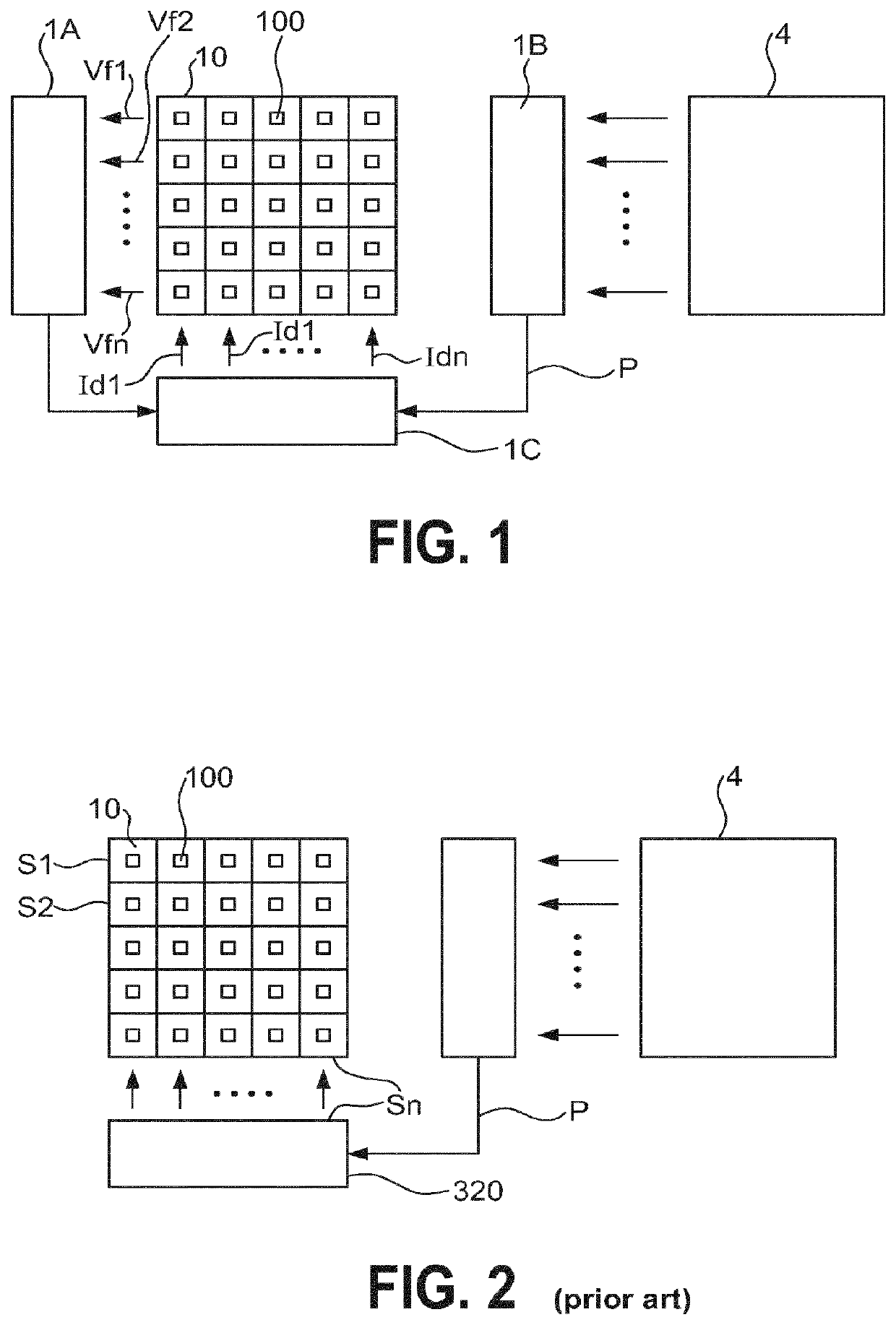
[0035]FIG. 1 shows a simplified block diagram of an embodiment of the inventive segmented flash system 1. The diagram shows a segmented flash 10, in this case a 5×5 square array of LEDs 100. The LEDs 100 of this array will illuminate twenty-five regions in a scene. In this exemplary embodiment, an illumination profile P can be provided by a depth map module 1B, which may for example compute the illumination profile P using information obtained by a photodetector 4. The illumination profile P specifies the required intensity or power required for each LED 100 to correctly illuminate the scene, assuming an equilibrium condition in which all LEDs 100 have essentially the same temperature. In this exemplary embodiment, the segmented flash system 1 also comprises a voltage measuring module 1A that measures the forward voltages Vf1, Vf2, . . . , Vfn of the LEDs 100 of the array. With this information, a controller 1C computes adjusted drive current values Id1_a, Id2_a, . . . , Idn_a for t...


PUM


Abstract

The invention describes a method of controlling a segmented flash (10) having a plurality of flash segments (S1, S2, . . . , Sn), which method comprises the steps of measuring the forward voltages (Vf1, Vf2, . . . , Vfn) of the flash segments (S1, S2, . . . , Sn); and adjusting the brightness of the flash segments (S1, S2, . . . , Sn) on the basis of the measured forward voltages (Vf1, Vf2, . . . , Vfn) to achieve a desired illumination profile (P) for the segmented flash (10). The invention further describes a segmented flash system (1) comprising a segmented flash (10) with a plurality of flash segments (S1, S2, . . . , Sn), wherein each flash segment (S1, S2, . . . , Sn) is arranged to illuminate a portion (20) of a scene (2); and a flash driver (11) adapted to perform the steps of the inventive method to adjust the brightness of the flash segments (S1, S2, . . . , Sn).

Description

FIELD OF THE INVENTION[0001]The invention describes a method of controlling a segmented flash system. The invention also describes a segmented flash system.BACKGROUND OF THE INVENTION[0002]When a conventional flash system is used in photographing a scene, any objects that are too close to the camera may suffer from overexposure and appear too “white” or pale in the image, while objects further away from the camera may not be sufficiently illuminated and appear too dark in the photograph or image. Developments in flash systems have led to a segmented flash, i.e. a flash made up of an array of light sources. The spectra of the light sources deployed in the segmented flash can be chosen to achieve a desired white balance. Each light source illuminates a region of the scene, so that the segmented flash generates an “illumination profile” or pattern. It is possible to determine the relative amount of light required to correctly illuminate or expose each region of the scene, for example b...

Claims


Application Information

Patent Timeline
Patent Type & Authority Applications(United States)
IPC IPC(8): G03B15/02H05B45/56H05B45/14H05B45/37G03B15/05H05B44/00
CPCG03B15/02H05B45/56G03B15/05H05B45/37H05B45/14H05B45/30H05B45/345H05B45/24G03B2215/0567H05B45/52
Inventor DERKS, HENK
Owner LUMILEDS
Why Eureka
Try Eureka