Fixing mechanism and computer chassis

a technology of fixing mechanism and computer chassis, which is applied in the direction of electrical apparatus casing/cabinet/drawer, electrical apparatus construction details, instruments, etc., can solve the problems of increasing production cost, requiring a lot of time and manpower, and reducing product competitiveness, so as to achieve the effect of reducing the production cost of the computer chassis and improving product competitiveness

Active Publication Date: 2018-10-09
LITE ON ELECTRONICS (GUANGZHOU) LTD +1
View PDF13 Cites 2 Cited by
  • Summary
  • Abstract
  • Description
  • Claims
  • Application Information

AI Technical Summary

Benefits of technology

[0007]The invention is directed to a computer chassis including the aforementioned fixing mechanism, which has a low production cost and high product competitiveness.
[0020]According to the above description, in the design of the fixing mechanism of the invention, the electronic device is adapted to be assembled in the main member, and the first locking member includes the fixing portion, the support portion and the stop portion, where the fixing portion includes the first part and the second part, the first part is connected to the main member and the support portion, and the stop portion is located on the bottom surface of the support portion. When the fixing mechanism assembled with the electronic device is assembled on the casing of the computer chassis, the second part of the fixing portion and the stop portion are respectively located in the first position limiting opening and the second position limiting opening of the circuit board, such that the first locking member is locked to the circuit board, and the support portion is located on the circuit board to support the electronic device, so as to fix the fixing mechanism in the casing. Through the aforementioned method, it is unnecessary to use other additional assembly components, so that the production cost of the computer chassis is effectively reduced to improve product competitiveness.

Problems solved by technology

However, to use the fastening members to fasten the fixing mechanism used for fixing the hard disk to the casing requires a large amount of fastening members, by which not only disassembly and installation require a lot of time and manpower, but also a production speed is slow, which increases a production cost.
In other words, such method is very unsuitable for the current popular trends of whole set assembly and tool-less disassembly.

Method used


Image

  • Fixing mechanism and computer chassis
  • Fixing mechanism and computer chassis
  • Fixing mechanism and computer chassis

Examples


Embodiment Construction

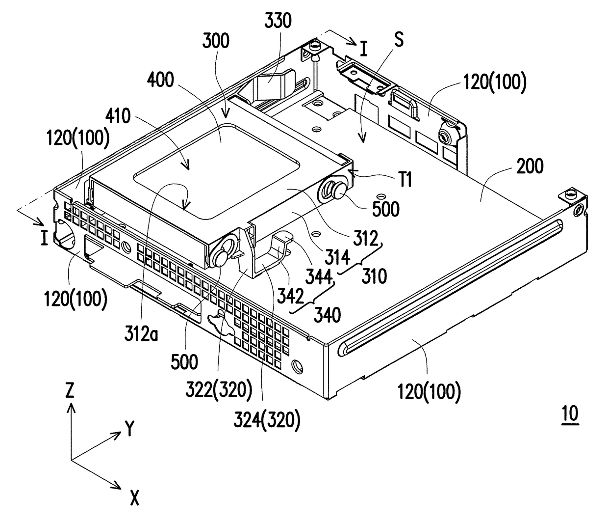
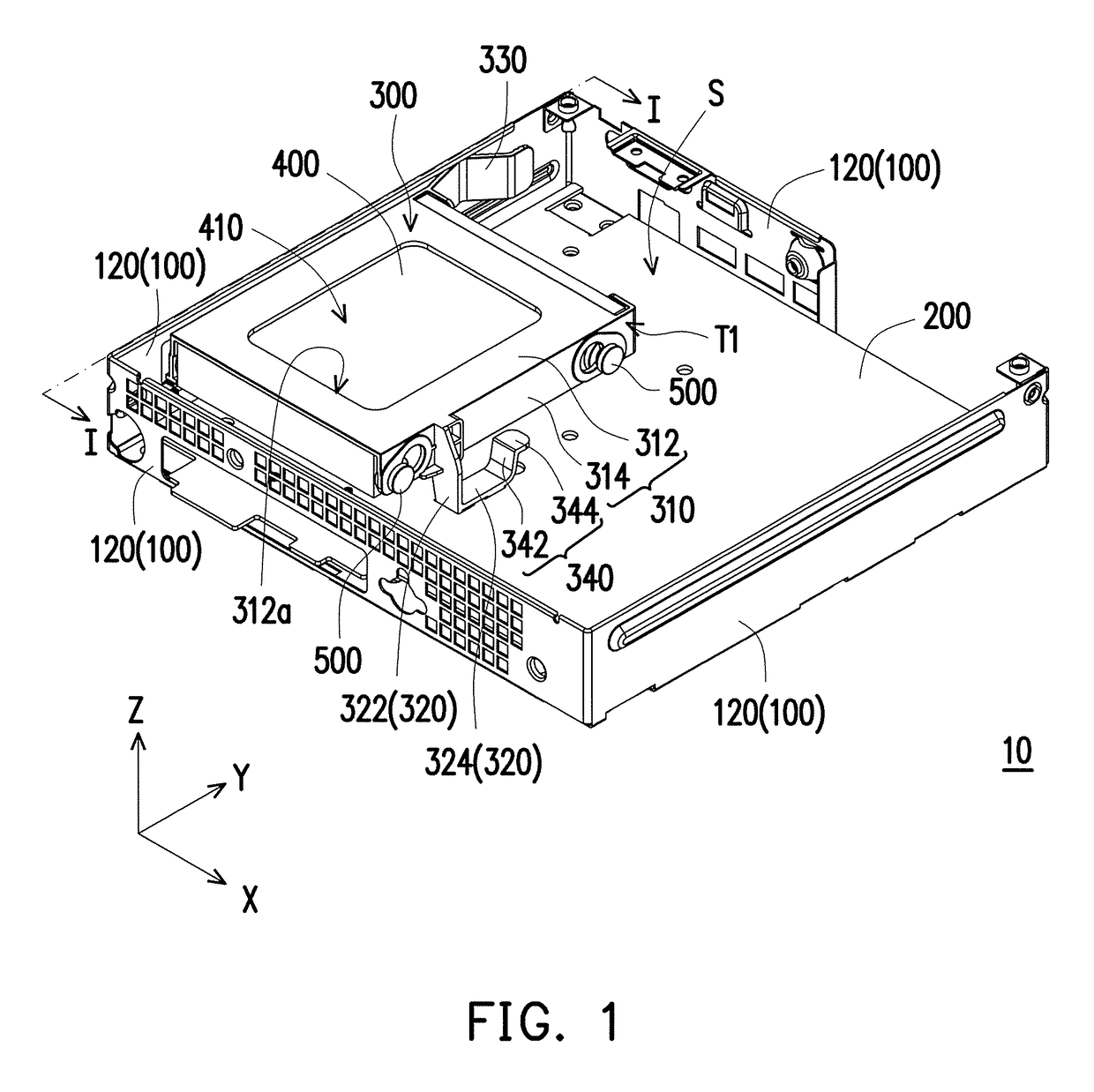
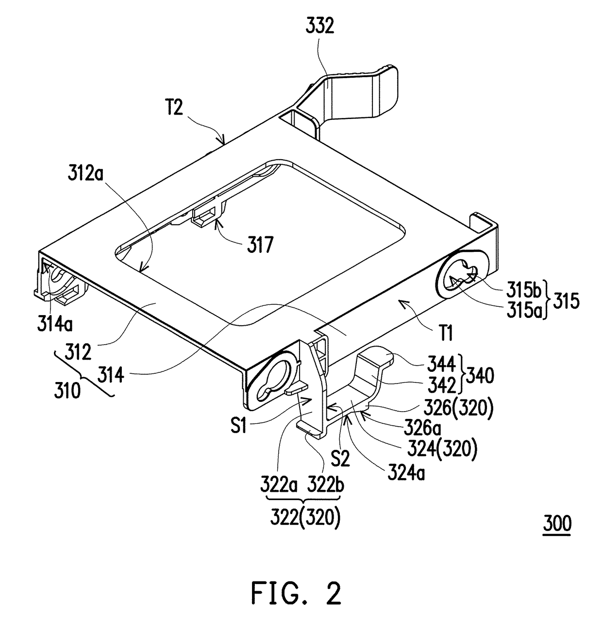
[0029]FIG. 1 is a three-dimensional (3D) view of a computer chassis according to an embodiment of the invention.FIG. 2 is a three-dimensional view of a fixing mechanism of the computer chassis of FIG. 1. FIG. 3 is an exploded view of the computer chassis of FIG. 1. FIG. 4 is a partial cross-sectional view of the computer chassis of FIG. 1. FIG. 5 is a partial 3D cross-sectional view of the computer chassis of FIG. 1. FIG. 6 is a partial 3D cross-sectional view of FIG. 1 along a section line I-I. For simplicity's sake, an electronic device is omitted in FIG. 6.

[0030]Referring to FIG. 1, FIG. 2, FIG. 3, FIG. 4 and FIG. 5, the computer chassis 10 of the present embodiment includes a casing 100, a circuit board 200, a fixing mechanism 300 and an electronic device 400. The casing 100 includes a bottom plate 110 and a plurality of side plates 120. The side plates 120 are connected to the bottom plate 110 and define an accommodating space S together with the bottom plate 110. The circuit b...


PUM

PropertyMeasurementUnit
forceaaaaaaaaaa
displacementaaaaaaaaaa
outer diameteraaaaaaaaaa

Abstract

A fixing mechanism and a computer chassis are provided. The fixing mechanism includes a main member and a first locking member. The first locking member includes a fixing portion, a support portion and a stop portion. The fixing portion includes a first part and a second part, and two ends of the first part are respectively connected to the main member and the second part. The support portion is connected to the fix portion, and the second part and the support portion are respectively located on two opposite surfaces of the first part. The stop portion is connected to the support portion, and located on a bottom surface of the support portion. An electronic device is assembled in the main member, and the first locking member is locked to a circuit board of a computer chassis to fix the fixing mechanism in a casing of the computer chassis.

Description

CROSS-REFERENCE TO RELATED APPLICATION[0001]This application claims the priority benefits of U.S. provisional application Ser. No. 62 / 459,608, filed on Feb. 16, 2017 and China application Ser. No. 201820023136.8, filed on Jan. 8, 2018. The entirety of each of the above-mentioned patent application is hereby incorporated by reference herein and made a part of this specification.BACKGROUND OF THE INVENTION[0002]Field of the Invention[0003]The invention relates to a fixing mechanism and a computer chassis, and particularly relates to fixing mechanism used for fixing an electronic device and a computer chassis including the fixing mechanism.[0004]Description of Related Art[0005]A hard disk is generally installed in internal of a computer chassis, and in order to securely install the hard disk in the computer chassis, fastening members (for example, screws or bolts) are mainly adopted to fasten a fixing mechanism used for fixing the hard disk to a casing of the computer chassis. However,...

Claims


Application Information

Patent Timeline
Patent Type & Authority Patents(United States)
IPC IPC(8): G06F1/16H05K5/00H05K7/00G06F1/18H05K7/14G11B33/12
CPCG06F1/187H05K7/1422G11B33/128G11B33/124
Inventor TSAI, JEN-WEICHIU, LIANG-CHENGHUANG, CHIH-CHENG
Owner LITE ON ELECTRONICS (GUANGZHOU) LTD
Why Eureka
Try Eureka