
Pneumatic radial tire with specified bead portions

a radial tire and pneumatic technology, applied in the direction of tire beads, heavy-duty vehicles, vehicle components, etc., can solve problems such as separation and troubl

Inactive Publication Date: 2018-10-16
TOYO TIRE & RUBBER CO LTD
View PDF16 Cites 0 Cited by
  • Summary
  • Abstract
  • Description
  • Claims
  • Application Information

AI Technical Summary

Benefits of technology

[0007]The present invention is made by taking the actual condition mentioned above into consideration, and an object of the present invention is to provide a pneumatic radial tire which suppresses troubles not only in a wind-up end of a carcass play, but also in an end portion of a steel protection layer, and is excellent in a durability of a bead portion.
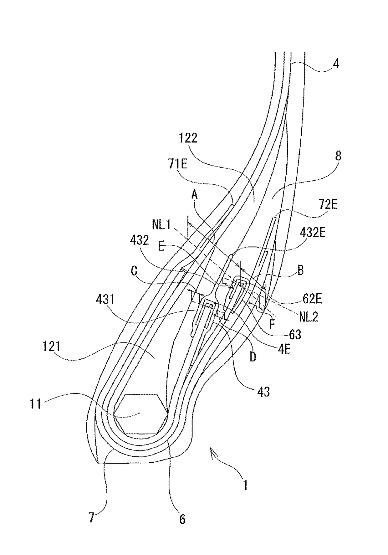
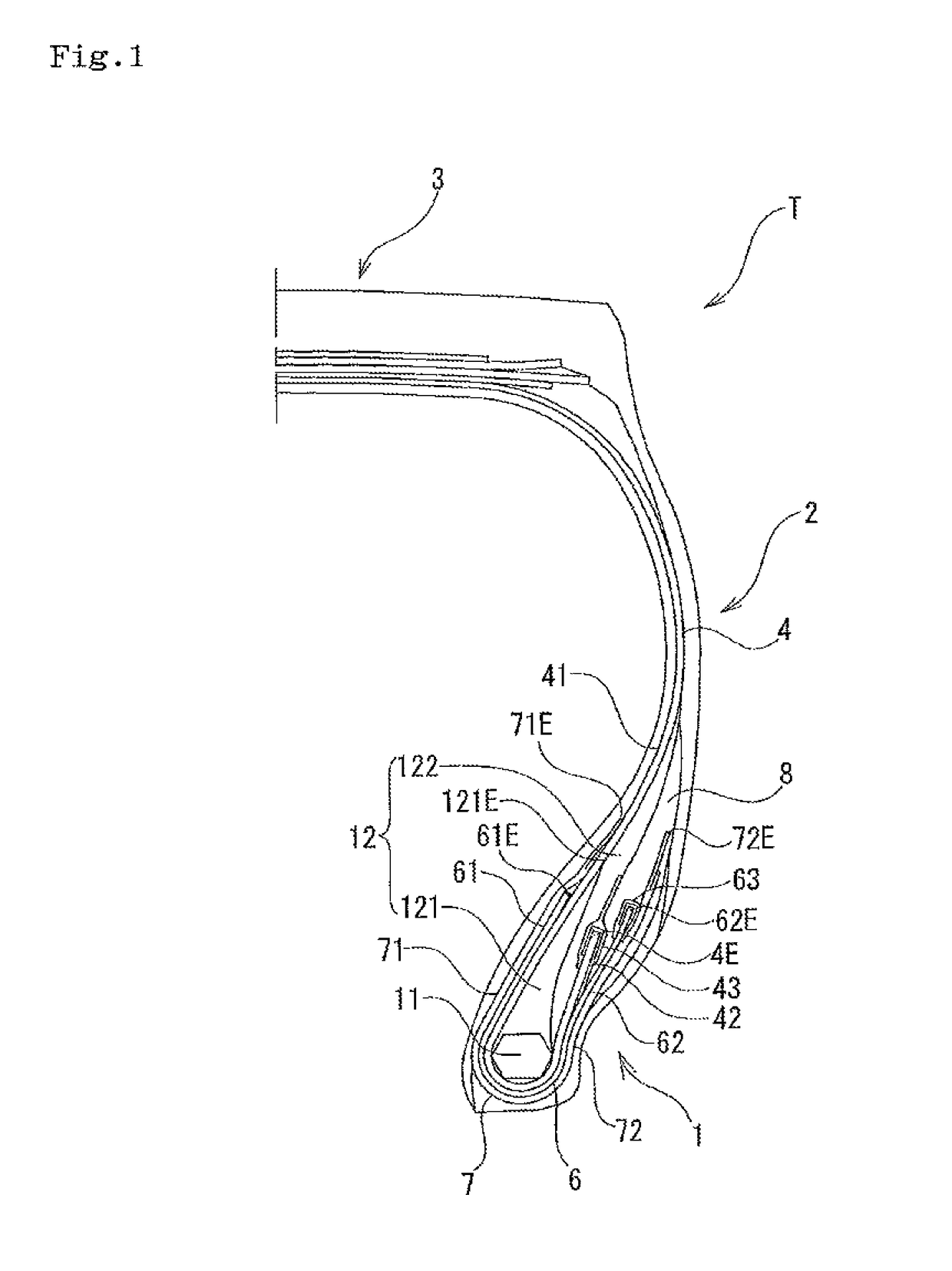
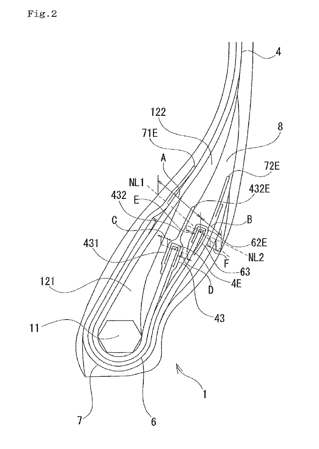
[0009]In the pneumatic radial tire according to the present invention, since the wind-up end of the steel protection layer is sandwiched by the reinforcing rubber, it is possible to suppress the trouble beginning at the end portion of the steel protection layer. Further, since the distance from the tire inner surface and the tire outer surface to the steel protection layer can be secured by setting the width A from the wind-up end of the steel protection layer to the tire inner surface and the width B from the wind-up end of the steel protection layer to the tire outer surface so as to satisfy the relationship mentioned above, it is possible to effectively suppress the trouble beginning at the end portion of the steel protection layer. Further, it is possible to suppress the trouble beginning at the wind-up end of the carcass ply by covering the wind-up end of the carcass ply with the ply cover member. Further, it is possible to effectively suppress the trouble beginning at the wind-up end of the carcass ply by setting the thickness C of the second bead filler and the thickness D of the reinforcing rubber which sandwich the ply cover member from both sides, so as to satisfy the relationship mentioned above.
[0011]According to the structure, it is possible to suppress the trouble beginning at the end portion of the steel protection layer by covering the wind-up end of the steel protection layer with the steel protection layer cover member. Further, it is possible to effectively suppress the trouble beginning at the end portion of the steel protection layer by setting the thicknesses E and F of the reinforcing rubbers sandwiching the steel protection layer from both sides so as to satisfy the relationship mentioned above.
[0013]According to the structure, since it is possible to reduce a strain in the wind-up end of the carcass ply by changing the rubber hardness of the rubber around the carcass ply little by little, it is possible to suppress the trouble beginning at the wind-up end of the carcass ply.
[0015]According to the structure, since the wind-up end of the steel protection layer can be protected by the extension portion of the ply cover member, it is possible to suppress the trouble beginning at the wind-up end of the steel protection layer.

Problems solved by technology

Conventionally, in a pneumatic radial tire which is used for a heavy vehicle particularly such as an industrial vehicle and a construction vehicle, there has been fear that a trouble such as a separation is caused while beginning at a wind-up end of a carcass ply which is wound around a bead core.
However, in the case that the steel protection layer as mentioned above is arranged, there is a risk that the trouble is generated while beginning at an end portion of the steel protection layer, and it has been found that there is room for improvement of the risk.

Method used


Image

  • Pneumatic radial tire with specified bead portions
  • Pneumatic radial tire with specified bead portions
  • Pneumatic radial tire with specified bead portions

Examples


examples

[0042]A durability test of the bead portion was carried out for specifically showing the structures and the effects of the present invention, and will be described below. A size of a tire supplied for the test was 11.00R20, and the tire was installed to a rim of 8.00V.

[0043]In the durability test, the tire was made to travel on a drum having a diameter of 1700 mm under a condition of an internal pressure of 830 kPa, a load of 3350 kgf (increased 10% per 24 hours) and a speed of 25 km / h, until the bead portion breaks down. Further, the durability was evaluated by an index number obtained by setting a result of a comparative example 1 to 100 in the traveling distance. Further, it was checked out whether or not any crack (obtained by progress of the separation) exists in the wind-up end of the steel protection layer and the wind-up end of the carcass ply, in the tire after the test travel.

[0044]The bead structure and the result of evaluation in each of the examples are shown in Table 1...


PUM


Abstract

A pneumatic radial tire includes a bead filler, a carcass ply, a steel protection layer, and an organic fiber protection layer. A reinforcing rubber sandwiches a wind-up end of the steel protection layer. A relationship of 1≤A / B≤2 is satisfied between a width A from the wind-up end of the steel protection layer to a tire inner surface, and a width B from the wind-up end of the steel protection layer to a tire outer surface. The wind-up end of the carcass ply is covered with a ply cover member. A relationship of 0.8≤D / C≤1.2 is satisfied between a thickness C of a second bead filler positioning between the ply cover member and a first bead filler, and a thickness D of the reinforcing rubber positioning between the ply cover member and the steel protection layer.

Description

BACKGROUND OF THE INVENTIONField of the Invention[0001]The present invention relates to a pneumatic radial tire which is characterized by a structure of a bead portion and has a high durability, and is particularly useful for a pneumatic radial tire for heavy load.Description of the Related Art[0002]Conventionally, in a pneumatic radial tire which is used for a heavy vehicle particularly such as an industrial vehicle and a construction vehicle, there has been fear that a trouble such as a separation is caused while beginning at a wind-up end of a carcass ply which is wound around a bead core. In order to address this problem, there has been known a method which improves a durability of a bead portion by arranging a protection layer along an outer side of the carcass ply of the bead portion as described in patent documents 1 to 3. However, there is a case that that pneumatic radial tire is used under a high internal pressure in some countries or areas, and it is necessary to further ...

Claims


Application Information

Patent Timeline
Patent Type & Authority Patents(United States)
IPC IPC(8): B60C15/06B60C15/00
CPCB60C15/0635B60C15/0607B60C15/0009Y10T152/10846B60C15/06B60C15/0603B60C15/0628B60C2015/065B60C2015/0617B60C2015/0621B60C2015/0625B60C2015/0692B60C2200/06Y10T152/10819Y10T152/10828Y10T152/10837B60C15/04B60C2015/042B60C2015/044
Inventor NAKAMATA, TSUNETAKA
Owner TOYO TIRE & RUBBER CO LTD
Learn More