
Vaporization type humidification unit, control method of vaporization type humidification unit, and sheet manufacturing apparatus

a technology of vaporization type and humidification unit, which is applied in the direction of air humidification system, lighting and heating apparatus, heating types, etc., can solve the problem that the finished sheet would end up being non-uniform, and achieve the effect of suppressing troubl

Active Publication Date: 2022-01-04
SEIKO EPSON CORP
View PDF10 Cites 0 Cited by
  • Summary
  • Abstract
  • Description
  • Claims
  • Application Information

AI Technical Summary

Benefits of technology

The patent text describes a device that controls the humidity in air by measuring the humidity and adjusting the air flow rate using two blowers. This allows for easy control of the humidification amount, and can be useful for preventing electrification troubles caused by high humidity. The technical effect is a more efficient and precise control of humidification in air.

Problems solved by technology

A problem is that, in the vaporization type humidifier disclosed in Japanese Unexamined Patent Application Publication No. 2005-24176, it is necessary to vary the air flow rate in order to control the humidification amount.
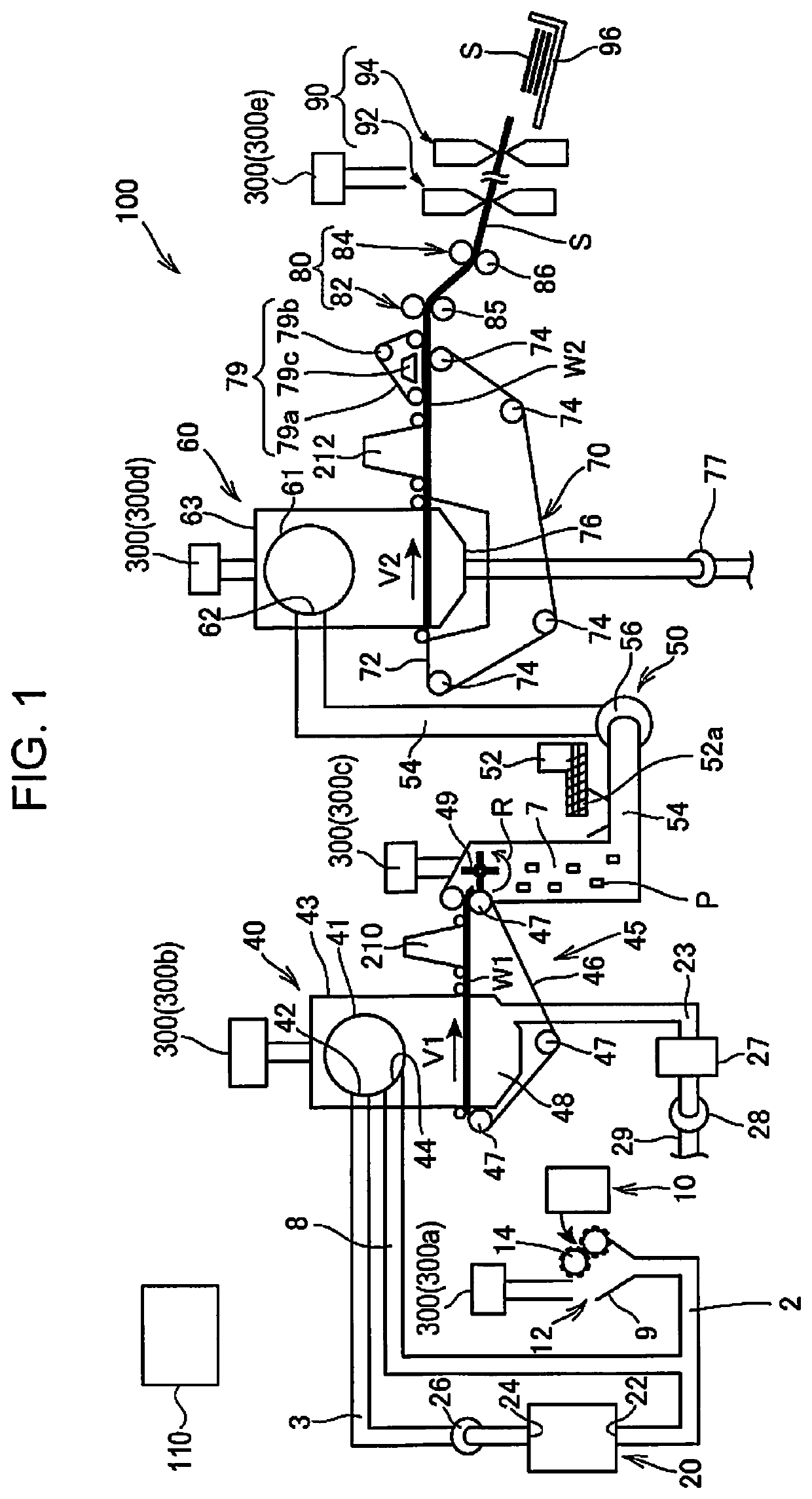
Therefore, when the humidifier described above is applied to a dry type waste paper recycling machine that uses air transport or an air raid method, a variation in the air flow rate influences the transport air of material and accumulation distribution of the material in a sheet formation unit that uses an air raid method such that there is a concern that a finished sheet would end up being non-uniform.

Method used


Image

  • Vaporization type humidification unit, control method of vaporization type humidification unit, and sheet manufacturing apparatus
  • Vaporization type humidification unit, control method of vaporization type humidification unit, and sheet manufacturing apparatus
  • Vaporization type humidification unit, control method of vaporization type humidification unit, and sheet manufacturing apparatus

Examples


modification example 1

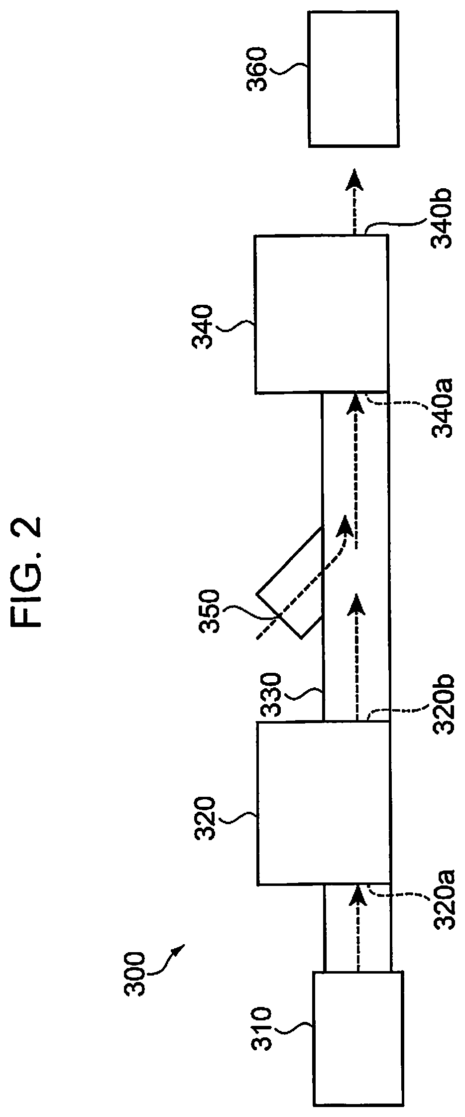
[0138]FIG. 5 is a schematic diagram showing a configuration of a vaporization type humidification unit 301 according to the modification example 1. In the embodiment described above, as shown in FIG. 2, the description was that the first blower 320 sucks the air that has passed through the vaporization unit 310, but this configuration is not limited thereto.

[0139]In the following, the vaporization type humidification unit 301 according to Modification Example 1 will be described. The components same as those of the embodiment will be denoted by the same reference numerals and the duplicate descriptions will be omitted.

[0140]As shown in FIG. 5, the vaporization type humidification unit 301 includes a vaporization unit 310 that evaporates moisture, a first blower 320 that discharges the air (sucked outside air) toward the vaporization unit 310, a transport tube 330 that is connected to the vaporization unit 310 and through which the air that has passed the vaporization unit 310 is tra...

modification example 2

[0144]The opening 350 is not limited to the idle of the transport tube 330, and the opening 350 may be provided in the vaporization unit 310. In this case, the opening 350 is installed on the side, past the humidification filter, of the transport tube 330 through which the humidification air is transported. In this way, the opening 350 is unnecessary in the transport tube 330 between the first blower 320 and the second blower 340, the structure of the vaporization type humidification unit 300 is simplified, and the degree of freedom of the shape of the transport tube 330 becomes high.

modification example 3

[0145]In the above embodiment, the description was that the number of rotations of the motor of the second blower 340 is controlled to be constant, but this configuration is not limited thereto. In the following, a vaporization type humidification unit 300 according to Modification Example 3 will be described.

[0146]When the transport tube 330 is sufficiently long, the influence of the variations of the air flow rate of the first blower 320 on the air flow rate of the second blower 340 is small. On the other hand, when the transport tube 330 is short, for example, the air flow rate of the second blower 340 is affected in some cases when the air flow rate of the first blower 320 varies. In such a case, a wind speed sensor is installed on the discharging side of the second blower 340, and, in accordance with the air flow rate of the first blower 320, the number of rotations of the motor of the second blower may be controlled based on the measured wind speed such that the air flow rate ...


PUM


Abstract

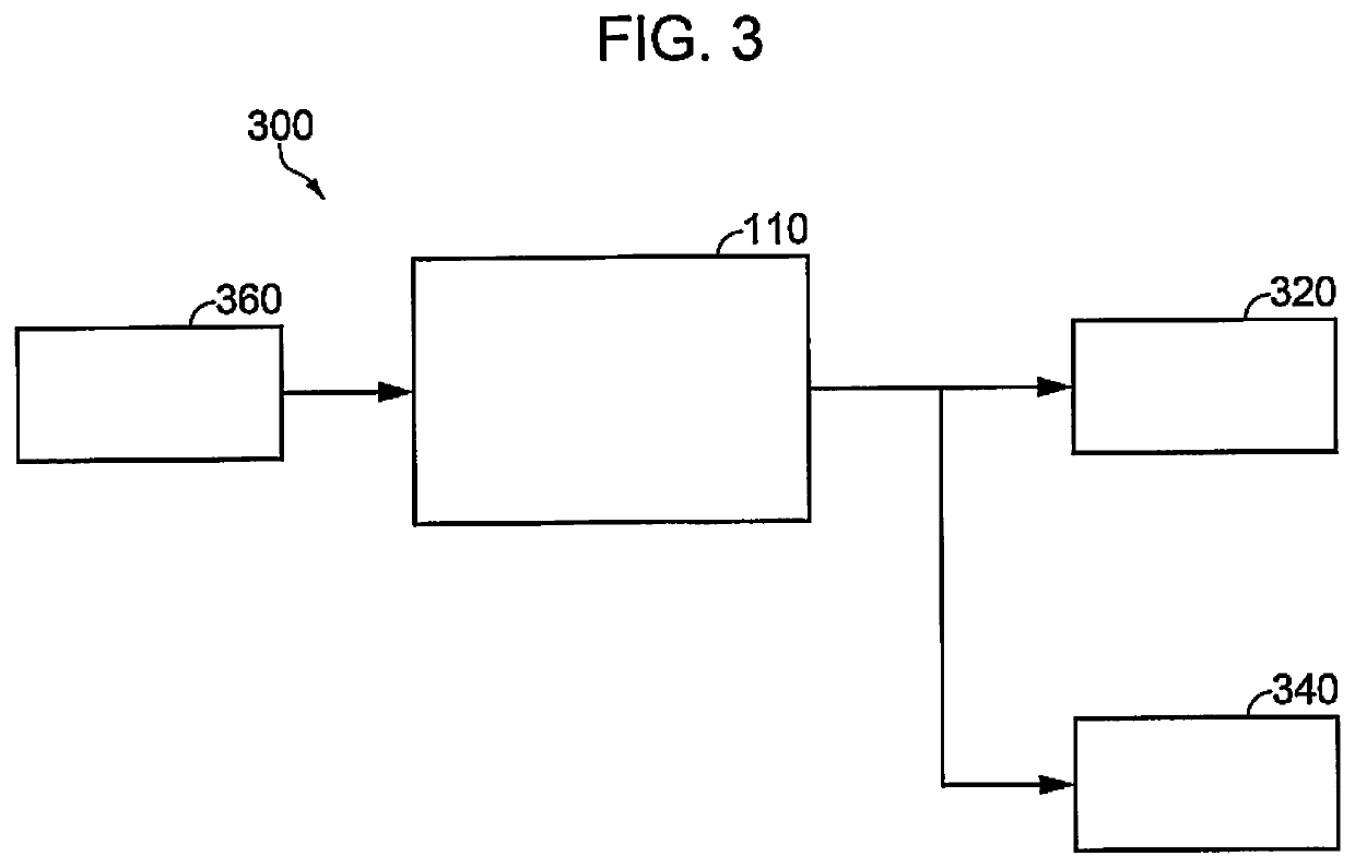
The vaporization type humidification unit includes a vaporization unit that evaporates moisture, a first blower that sucks humidification air humidified by the vaporization unit, a transport tube that is connected to the first blower and through which the air discharged from the first blower is transported, a second blower connected to the transport tube and discharging the humidification air discharged from the first blower side toward outside, an opening provided in a middle of the transport tube, a humidity measurement unit installed on a discharging side of the second blower, and a control unit that controls an air flow rate discharged from the first blower and the second blower, in which the control unit controls the air flow rate discharged from the second blower to a desired value and controls the air flow rate discharged from the first blower based on a humidity measured by the humidity measurement unit.

Description

CROSS-REFERENCE TO RELATED APPLICATIONS[0001]This application is a U.S. National stage application of International Patent Application No. PCT / JP2017 / 039968, filed on Nov. 6, 2017, which claims priority under 35 U.S.C. § 119(a) to Japanese Patent Application No. 2016-223853, filed in Japan on Nov. 17, 2016. The entire disclosure of Japanese Patent Application No. 2016-223853 is hereby incorporated herein by reference.TECHNICAL FIELD[0002]The present invention relates to a vaporization type humidification unit, a control method of a vaporization type humidification unit, and a sheet manufacturing apparatus.BACKGROUND ART[0003]In general, as disclosed in Japanese Unexamined Patent Application Publication No. 2005-24176, as a control method of a vaporization type humidifier, there is known a vaporization type humidifier that controls the number of rotations of a blower so as to supply necessary humidification amount and controls humidification amount by controlling air flow rate based ...

Claims


Application Information

Patent Timeline
Patent Type & Authority Patents(United States)
IPC IPC(8): D21G7/00D21G9/00F24F3/14F24F6/00F24F6/12D04H1/732F24F6/04
CPCD21G7/00D04H1/732D21G9/0009F24F3/14F24F6/00F24F6/04F24F6/12D21F9/00
Inventor INAGAKI, YUTASAITA, HIROYASUTSUJINO, KIYOSHISAITO, YUTAKANAKAMURA, MASAHIDE
Owner SEIKO EPSON CORP
Learn More