
Electrical connector

a technology of electrical connectors and connectors, which is applied in the manufacture of contact parts, coupling device connections, instruments, etc., can solve the problems of increasing molding difficulty and increasing and increasing the crosstalk between conductive terminals, so as to reduce the production cost of electrical connectors and avoid crosstalk problems of signal transmission. , the effect of reducing the difficulty of molding

Active Publication Date: 2018-10-16
LOTES
View PDF47 Cites 7 Cited by
  • Summary
  • Abstract
  • Description
  • Claims
  • Application Information

AI Technical Summary

Benefits of technology

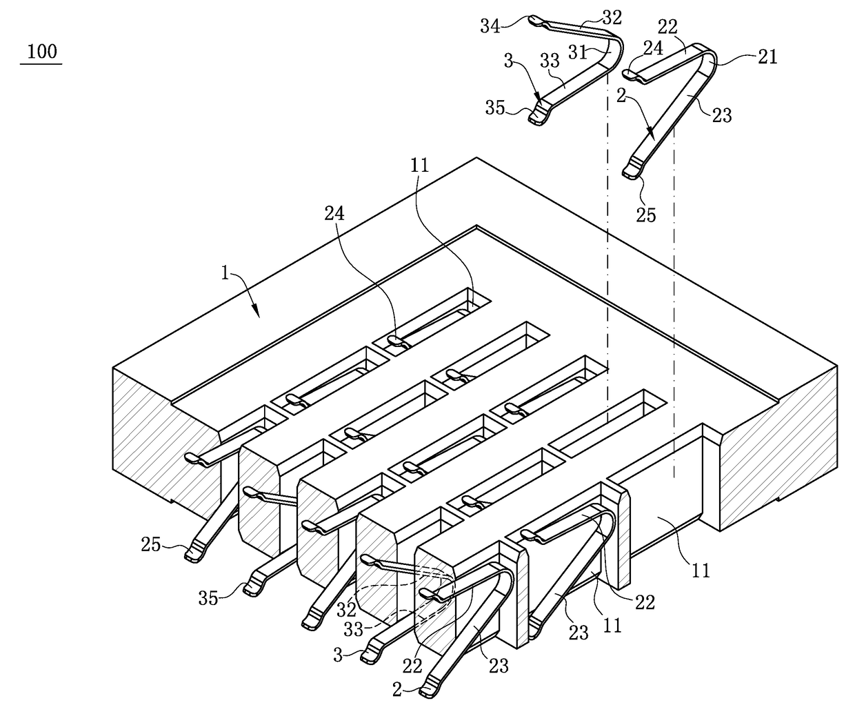
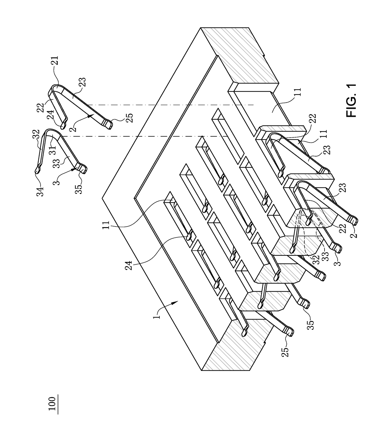
[0022]The directly facing area between the adjacent terminals is reduced by setting at least two types of terminals with different structures, thereby alleviating a crosstalk problem of signal transmission between the terminals; and the metal frame body or the metal sheet does not need to be additionally arranged at the periphery of the insulating body or in the insulating body, so that parts of the electrical connector are reduced, the molding difficulty is reduced and the production cost of the electrical connector is reduced.

Problems solved by technology

However, the arrangement density of the conductive terminals is increased continuously along with the increasing of information transmission quantity, so that crosstalk between the conductive terminals is increasingly serious to influence the signal transmission quality.
However, the two electrical connectors at least have the following disadvantages: in order to alleviate the crosstalk problem between the terminals, the metal frame is arranged at the periphery of the insulating body or the metal sheet is arranged in the insulating body, so that parts of the electrical connector are increased, and the molding difficulty and the production cost of the electrical connector are increased.
Therefore, a heretofore unaddressed need exists in the art to address the aforementioned deficiencies and inadequacies.

Method used


Image

  • Electrical connector
  • Electrical connector
  • Electrical connector

Examples


Embodiment Construction

[0035]The present invention is more particularly described in the following examples that are intended as illustrative only since numerous modifications and variations therein will be apparent to those skilled in the art. Various embodiments of the invention are now described in detail. Referring to the drawings, like numbers indicate like components throughout the views. As used in the description herein and throughout the claims that follow, the meaning of “a”, “an”, and “the” includes plural reference unless the context clearly dictates otherwise. Also, as used in the description herein and throughout the claims that follow, the meaning of “in” includes “in” and “on” unless the context clearly dictates otherwise. Moreover, titles or subtitles may be used in the specification for the convenience of a reader, which shall have no influence on the scope of the present invention.

[0036]It will be understood that when an element is referred to as being “on” another element, it can be di...


PUM


Abstract

An electrical connector includes an insulating body having multiple receiving slots, and multiple first terminals and multiple second terminals respectively received in the receiving slots. Each first terminal has a first connecting portion, a first elastic arm bending and upward extending from the first connecting portion, and a first conducting arm bending and extending from the first connecting portion. Each second terminal has a second connecting portion, a second elastic arm bending and extending upward from the second connecting portion, and a second conducting arm bending and extending from the second connecting portion. A bent position between each of the first connecting portions and a corresponding one of the first elastic arms is higher than a bent position between each of the second connecting portions and a corresponding one of the second elastic arms.

Description

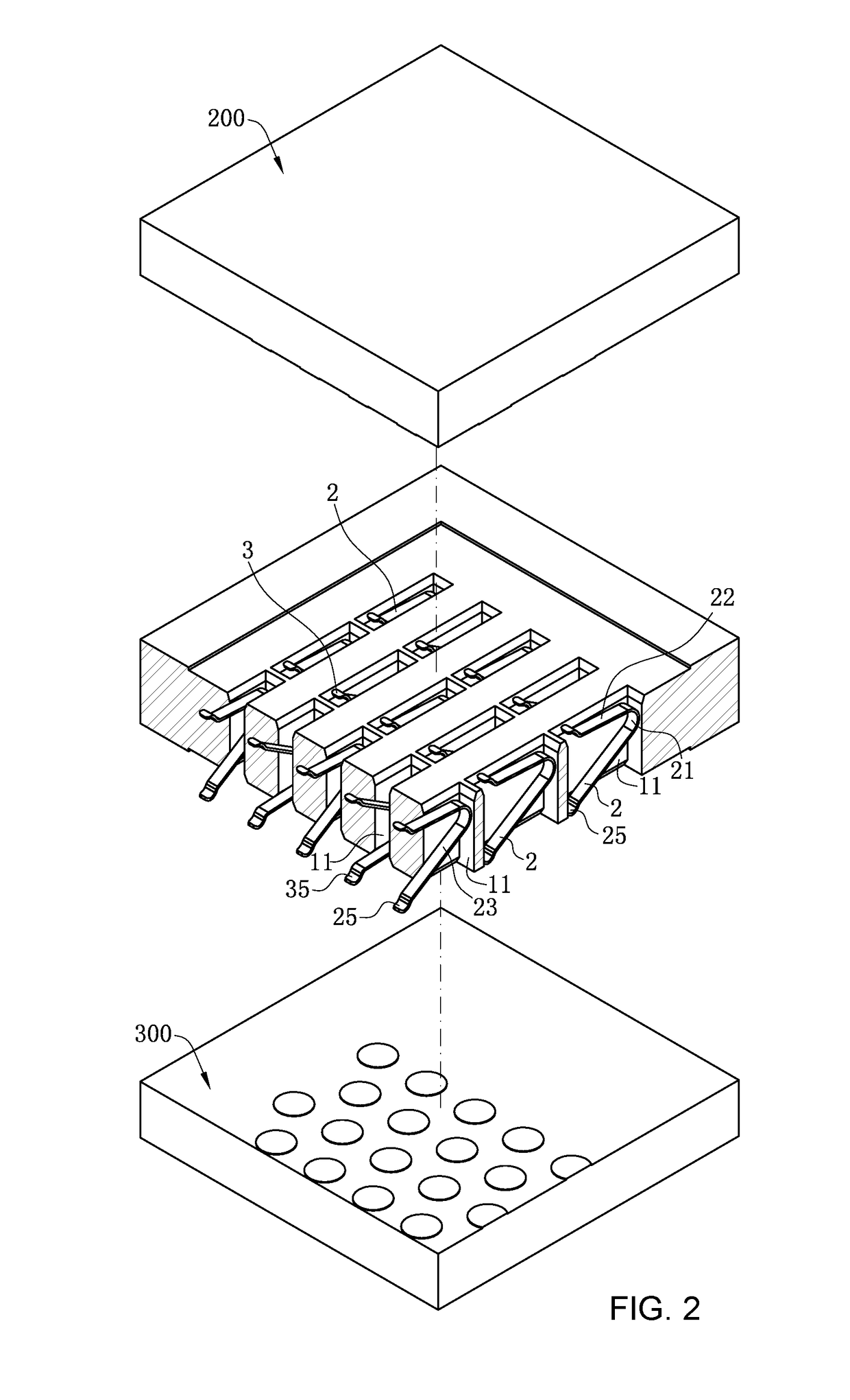
CROSS-REFERENCE TO RELATED APPLICATION[0001]This non-provisional application claims priority to and benefit of, under 35 U.S.C. § 119(a), Patent Application No. 201720053916.2 filed in P.R. China on Jan. 18, 2017, the entire content of which is hereby incorporated by reference.FIELD OF THE INVENTION[0002]The present invention relates to an electrical connector, and more particularly to a land grid array electrical connector that is used for electrically connecting a chip module to a circuit board.BACKGROUND OF THE INVENTION[0003]Due to stable electrical properties, electrical connectors have been widely applied to electronic fields, such as computers. An electrical connector for electrically connecting a chip module to a circuit board commonly includes an insulating body and conductive terminals received in the insulating body. The conductive terminals are used for transmitting signals between the chip module and the circuit board. However, the arrangement density of the conductive ...

Claims


Application Information

Patent Timeline
Patent Type & Authority Patents(United States)
IPC IPC(8): H01R12/00G01R1/067H01R12/71H01R13/41H01R13/24H01R43/02H01R43/16
CPCH01R13/2435G01R1/06716H01R12/714H01R13/41H01R13/2492H01R43/16H01R43/0249H01R43/0256H01R13/6461H05K7/1069
Inventor JU, TED
Owner LOTES
Learn More