Electrical connector with stabilizing grounding member

a technology of electrical connectors and grounding members, which is applied in the direction of coupling contact members, coupling protective earth/shielding arrangements, coupling device connections, etc., can solve the problems of electrical connector high-frequency transmission performance, electrical connector signal transmission affected, and unaddressed need in the art, etc., to reduce electromagnetic interference, enhance grounding effect of electrical connectors, and expand grounding area

Active Publication Date: 2018-10-16
LOTES
View PDF22 Cites 8 Cited by
  • Summary
  • Abstract
  • Description
  • Claims
  • Application Information

AI Technical Summary

Benefits of technology

[0007]In one aspect, the present invention relates to an electrical connector capable of reducing electromagnetic interference. By arranging a ground member in the electrical connector to urge against a shielding shell to form grounding, the grounding effect of the electrical connector is enhanced.
[0023]Compared with the related art, certain embodiments of the present invention arrange the ground member between the two adjacent first terminals or the two adjacent second terminals, the ground member is provided with the third contacting portion, the third contacting portion only urges against the shielding shell, consequently, a ground portion is added, the grounding area is enlarged, the grounding effect of the electrical connector is enhanced, electromagnetic interference is decreased, and the high-frequency transmission performance of the electrical connector is guaranteed.

Problems solved by technology

However, since the soldering portion is only soldered onto the circuit board for grounding, if the soldering portion is soldered poorly or gets loose, the signal transmission of the signal terminals will be affected, and as a result, the high-frequency transmission performance of the electrical connector will be affected.
Therefore, a heretofore unaddressed need exists in the art to address the aforementioned deficiencies and inadequacies.

Method used


Image

  • Electrical connector with stabilizing grounding member
  • Electrical connector with stabilizing grounding member
  • Electrical connector with stabilizing grounding member

Examples


first embodiment

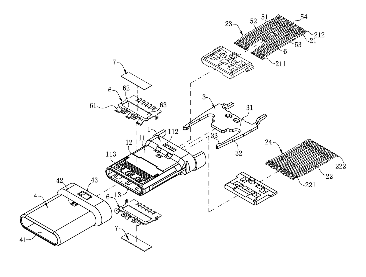
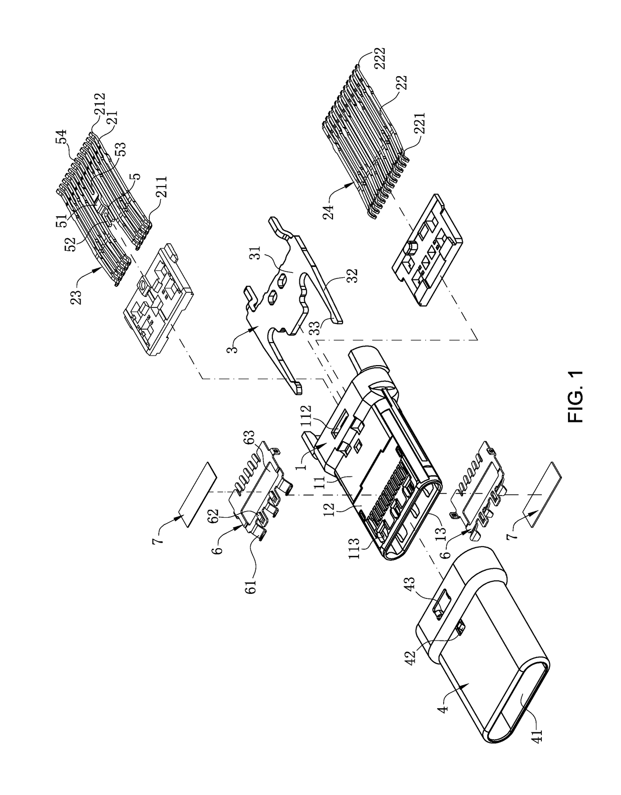
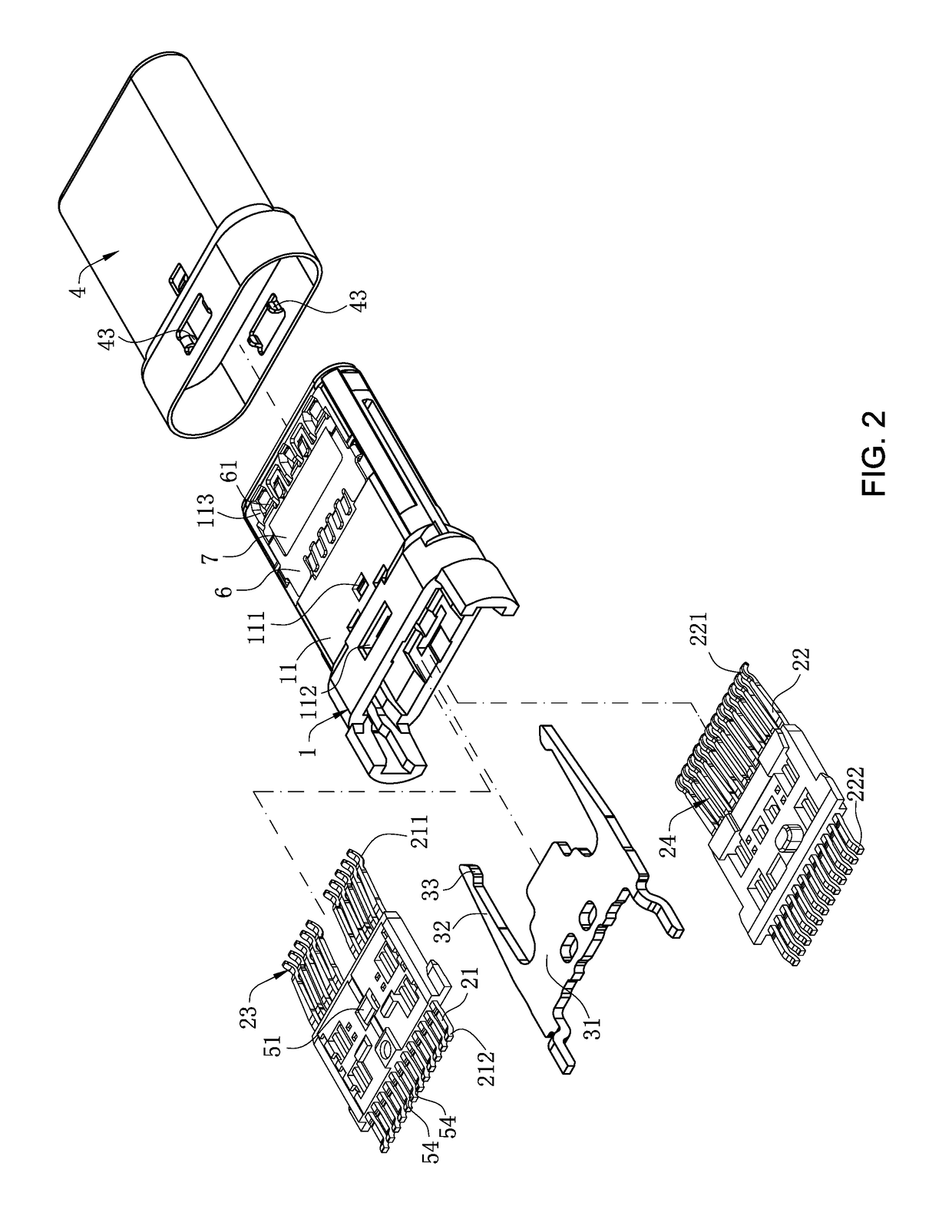
[0041]FIGS. 1 and 2 show the present invention. The insulating body 1 has a base 11, and an upper board 12 and a lower board 13 located at one side of the base 11. The insulating body 1 is concavely provided with a through hole 111 in the base 11. The base 11 is concavely provided with a positioning slot 112. The upper board 12 and the lower board 13 are located in the insertion space 41. The front ends of the upper board 12 and the lower board 13 are provided respectively with three holes, and the holes communicate with the insertion space 41.

[0042]The first terminal group 23 and the second terminal group 24 are provided respectively with multiple first terminals 21 and multiple second terminals 22. Each first terminal 21 and each second terminal 22 are provided respectively with a first contacting portion 211 and a second contacting portion 221, and the first contacting portions 211 and the second contacting portions 221 are exposed in the insertion space 41. Each first terminal 2...

second embodiment

[0047]FIGS. 6-8 show the present invention. The second embodiment is different from the first embodiment in that: the insulating body 1 is provided with a base 11, a tongue 14 extends from one side of the base 11, the first contacting portions 211 are exposed upwardly at the tongue 14, and the second contacting portions 221 are exposed downwardly at the tongue 14; the base 11 is provided with a groove 114, the third contacting portion 51 is exposed in the groove 114 and urges against the shielding shell 4 (as shown in FIG. 9), and detailed description is not made here.

[0048]In summary, the electrical connector according to certain embodiments of the present invention, among other things, has the following beneficial advantages:

[0049](1) The present invention arranges the ground member 5 between the two adjacent first terminals 21 or the two adjacent second terminals 22, the ground member 5 is provided with the third contacting portion 51, the third contacting portion 51 only urges a...


PUM


Abstract

An electrical connector includes an insulating body, a shielding shell wrapping the insulating body to form an insertion space, and a first terminal group and a second terminal group fixed in an upper row and a lower row in the insulating body. The first terminal group and the second terminal group have multiple first terminals and multiple second terminals. Each first terminal and each second terminal are provided respectively with a first contacting portion and a second contacting portion. The first contacting portions and the second contacting portions are exposed in the insertion space. A ground member is arranged between two adjacent first terminals or two adjacent second terminals. The ground member has a third contacting portion. The third contacting portion only urges against the shielding shell.

Description

CROSS-REFERENCE TO RELATED APPLICATION[0001]This application claims priority and the benefit of U.S. Provisional Application No. 62 / 404,395, filed on Oct. 5, 2016, the entire contents of which are hereby incorporated by reference.FIELD OF THE INVENTION[0002]The present invention relates to an electrical connector, and more particularly to an electrical connector capable of reducing electromagnetic interference.BACKGROUND OF THE INVENTION[0003]With the development of electronic technology, the frequency and speed of signals transmitted by an electrical connector tend to be higher. Therefore, the requirement for a shielding structure of the electrical connector is higher. It is required that the shielding structure have a higher and more stable grounding effect, so as to meet that the requirement of modern society for a high-frequency transmission performance of the electronic connector can be met.[0004]An existing electrical connector with a shielding structure includes an insulating...

Claims


Application Information

Patent Timeline
Patent Type & Authority Patents(United States)
IPC IPC(8): H01R13/646H01R43/02H01R13/6597H01R13/6594H01R13/631H01R9/03H01R13/6591H01R13/20H01R24/60H01R13/6581H01R13/652H01R13/648H01R13/04H01R13/405
CPCH01R13/646H01R9/03H01R13/04H01R13/20H01R13/405H01R13/631H01R43/0256H01R13/652H01R13/6581H01R13/6591H01R13/6594H01R13/6597H01R24/60H01R13/6485
Inventor JU, TED
Owner LOTES
Why Eureka
Try Eureka