Supercharge Your Innovation With Domain-Expert AI Agents!

Battery management system for outputting signal, capable analyzing whether error has occured, and battery driving system including same

a battery management system and outputting signal technology, applied in battery/fuel cell control arrangement, battery/discharge state control of all secondary battery cells or etc., can solve the problem of difficult to identify whether an error occurred in the battery management unit itself, and the limitation of the charge/discharge state of all secondary battery cells or the plurality of battery modules using a single battery management system

Active Publication Date: 2018-10-23
LG ENERGY SOLUTION LTD
View PDF14 Cites 1 Cited by
  • Summary
  • Abstract
  • Description
  • Claims
  • Application Information

AI Technical Summary

Benefits of technology

The patent allows for the detection of errors in battery management systems by analyzing signals received from external devices. It can identify the specific location and type of error, providing more precise information on the issue.

Problems solved by technology

Because the battery pack of the multi-module structure includes a plurality of secondary battery cells, there is a limitation in controlling the charge / discharge state of all the secondary battery cells or the plurality of battery modules using a single battery management system.
However, when a circuit or wiring used to transmit the notification of whether an error occurred is faulty, a signal indicating whether an error occurred is not transmitted despite an error or malfunction occurred in the battery management unit, and in contrast, the battery management unit is in normal state, but nevertheless, a signal indicating that an error occurred in the battery management unit may be transmitted.
Accordingly, it is difficult to identify whether an error occurred in the battery management unit itself, or a circuit, a switching device, or a signal line inside the battery management system.

Method used


Image

  • Battery management system for outputting signal, capable analyzing whether error has occured, and battery driving system including same
  • Battery management system for outputting signal, capable analyzing whether error has occured, and battery driving system including same
  • Battery management system for outputting signal, capable analyzing whether error has occured, and battery driving system including same

Examples


Embodiment Construction

[0035]Hereinafter, preferred embodiments of the present disclosure will be described in detail with reference to the accompanying drawings. Prior to the description, it should be understood that the terms used in the specification and the appended claims should not be construed as limited to general and dictionary meanings, but interpreted based on the meanings and concepts corresponding to technical aspects of the present disclosure on the basis of the principle that the inventor is allowed to define terms appropriately for the best explanation. Therefore, the description proposed herein is just a preferable example for the purpose of illustrations only, not intended to limit the scope of the disclosure, so it should be understood that other equivalents and modifications could be made thereto without departing from the spirit and scope of the disclosure.

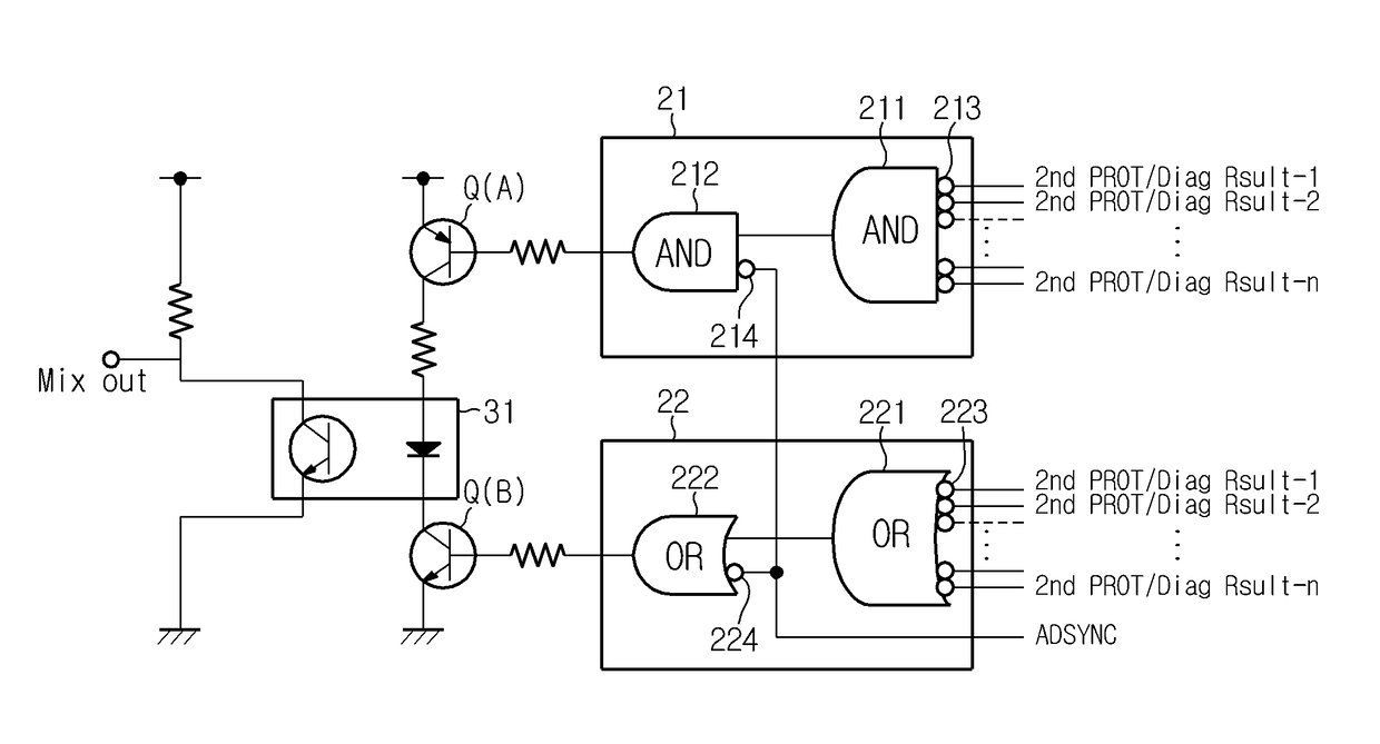
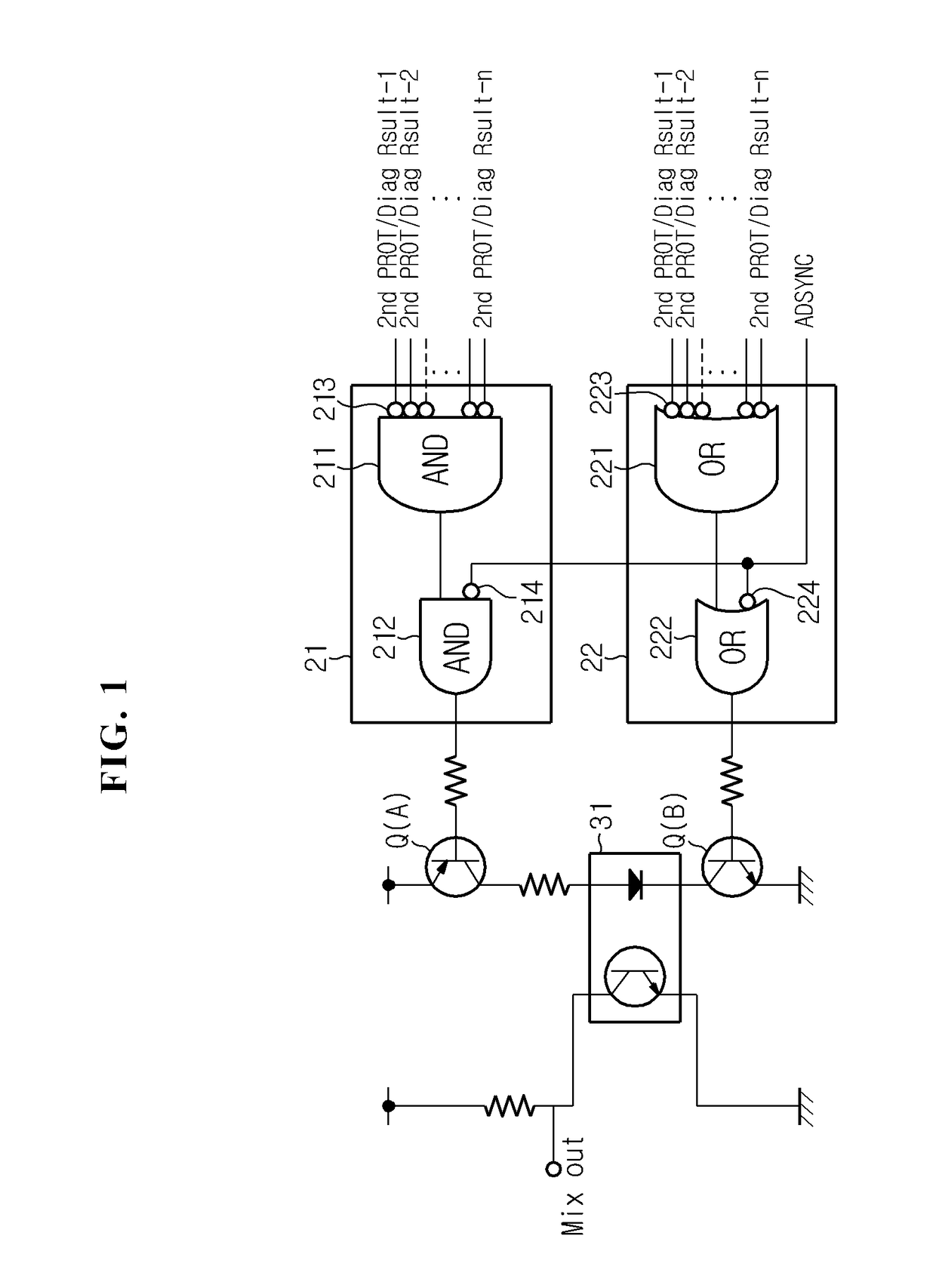
[0036]FIG. 1 is a diagram showing an example in which a portion of a battery management system according to the present disclosure...


PUM


Abstract

Disclosed is a battery management system for outputting a signal, capable of determining whether an error has occurred. The battery management system, according to the present invention, includes a plurality of battery management units measuring the voltage of a secondary battery and controlling the charging and discharging thereof. The battery management units output signals when the secondary battery managed thereby is overcharged or overdischarged and errors occur in the units themselves. At this time, the plurality of battery management units output the signals to lines connected in series. In the battery management system, according to the present invention, the waveforms of the signals to be output change according to the amount of current flowing in the lines connected in series.

Description

TECHNICAL FIELD[0001]The present disclosure relates to a battery management system, and more particularly, to a battery management system that outputs a signal capable of analyzing whether an error is in the battery management system itself when transmitting a signal to an external device.[0002]The present application claims priority to Korean Patent Application No. 10-2014-0017848 filed in the Republic of Korea on Feb. 17, 2014, and Korean Patent Application No. 10-2015-0023856 filed in the Republic of Korea on Feb. 17, 2015, the disclosures of which are incorporated herein by reference.BACKGROUND ART[0003]Due to its characteristics of being easily applicable to various products and electrical characteristics such as a high energy density, a secondary battery is not only commonly applied to a portable device, but universally applied to an electric vehicle (EV), a hybrid electric vehicle (HEV), or an energy storage system that runs on an electrical driving source. This secondary bat...

Claims


Application Information

Patent Timeline
Patent Type & Authority Patents(United States)
IPC IPC(8): H02J7/00G01R31/36B60L11/18
CPCG01R31/3651B60L11/1851B60L11/1861H02J7/0026G01R31/3658H02J7/0021G01R31/3606B60L3/04B60L2240/547B60L2240/549B60L58/19B60L58/15G01R31/396Y02T10/70Y02E60/10H02J7/0048H02J7/0014H01M10/48G01R31/367G01R31/392G01R31/371B60L58/10G01R31/382B60L3/0046
Inventor KANG, JU-HYUNEGUCHI, YASUHITOTANINA, SHOJI
Owner LG ENERGY SOLUTION LTD
Features
  • R&D
  • Intellectual Property
  • Life Sciences
  • Materials
  • Tech Scout
  • Unparalleled Data Quality
  • Higher Quality Content
  • 60% Fewer Hallucinations
Learn More