Self-locking figure eight hook

a self-locking, figure eight technology, applied in mechanical equipment, transportation and packaging, ropes/pulleys, etc., can solve the problems of weak devices that do not provide a simple structure, and achieve the effects of improving security, enhancing locking, and increasing weigh

Inactive Publication Date: 2018-10-30
SHAPIRO BARRY
View PDF5 Cites 4 Cited by
  • Summary
  • Abstract
  • Description
  • Claims
  • Application Information

AI Technical Summary

Benefits of technology

[0005]In general, the various embodiments of the disclosure are directed to a self-locking hook, wherein the weight of an object to be supported by the hook serves to enhance locking, assuring that the object is securely supported. Up to strength limits on the material used in forming the apparatus, the security is improved as weight increases, because of this self-locking action.

Problems solved by technology

Despite their advantages, these devices do not provide a simple structure that is strong and locks securely to prevent the suspended article from falling.

Method used


Image

  • Self-locking figure eight hook
  • Self-locking figure eight hook
  • Self-locking figure eight hook

Examples


Embodiment Construction

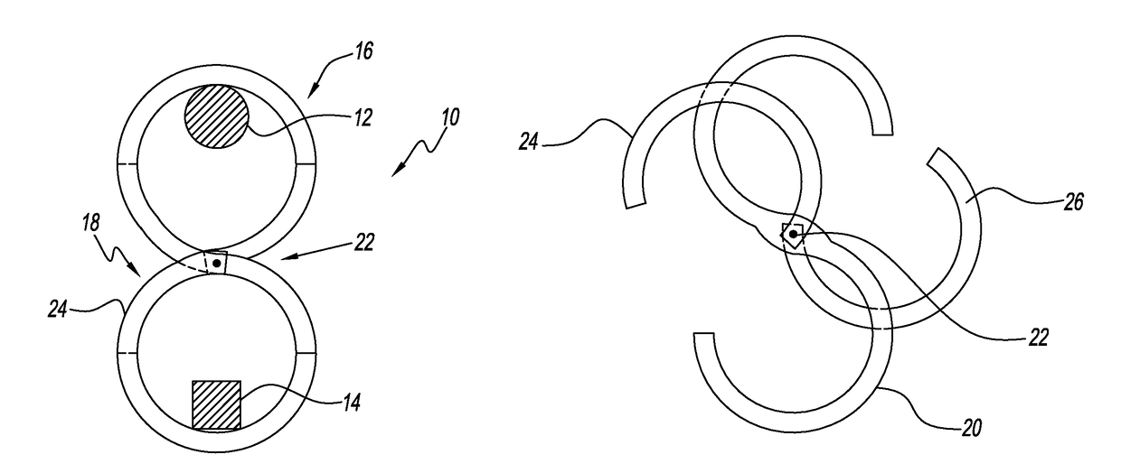
[0018]In FIG. 1 illustrates the apparatus 10 disclosed herein in a locked configuration supported by a support member 12 and the apparatus supporting an object 14. Object 12, shown in cross-section may be a horizontally extending pole or rod or a portion of a hook, or other supporting member that can be received within a first, upper portion 16 of apparatus 10. Object 14 can be any member that needs to be supported or suspended from apparatus 10 below support member 12. It can be a hook, a rod or of any size and shape, as long as it can be received in the opening in the lower portion 18 of apparatus 10.

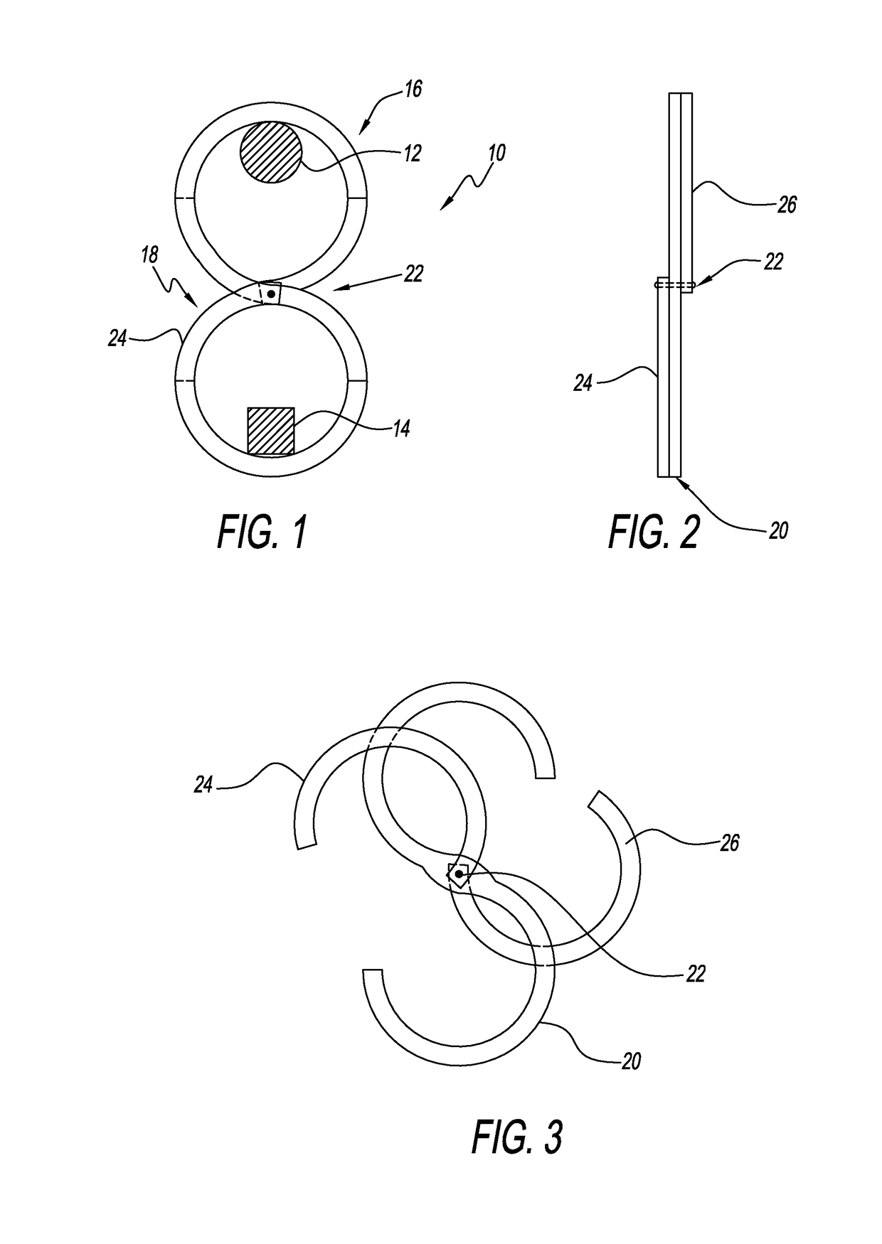
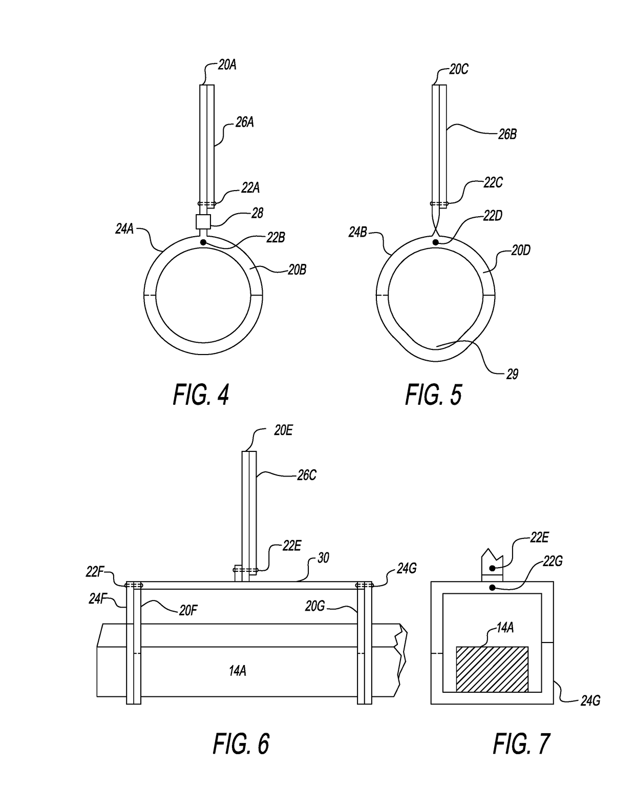
[0019]Referring to FIG. 1, FIG. 2 and FIG. 3, apparatus 10 includes four components. The first component is a flat, rigid S shaped member 20, having a first surface and a second surface parallel to the first surface. S shaped member 20 may be formed of steel or other suitable material having sufficient thickness and strength to support object 14.

[0020]The second component of apparatus...


PUM


Abstract

A self-locking hook includes an S shaped member having a first surface and a second surface, a first portion for receiving a support member and a second portion for supporting an object; a pivot pin extending through an opening in the S shaped member and extending from the first surface and the second surface; a first locking member held by the pivot pin to pivot against the first surface to defines an opening so that the first portion can engage the support member, to a position where the first locking member and the first portion form a closed loop to surround the support member; and a second locking member held by the pivot pin to pivot against the second surface to define an opening so that the second portion can receive an object to be supported, to a second position where the second locking member and the second portion form a closed loop.

Description

BACKGROUND OF THE DISCLOSURE[0001]1. Field of the Disclosure[0002]The present disclosure relates to apparatus for hanging articles. More particularly, it relates to hook type apparatus that can be used to hang an article on a pole or protuberance, and to keep the article securely suspended.[0003]2. Description of the Related Art[0004]Conventional hooks are described in, for example, U.S. Pat. No. 2,456,374 to Carter and European Patent Application 0362087 of Fister et al. Despite their advantages, these devices do not provide a simple structure that is strong and locks securely to prevent the suspended article from falling.SUMMARY OF THE DISCLOSURE[0005]In general, the various embodiments of the disclosure are directed to a self-locking hook, wherein the weight of an object to be supported by the hook serves to enhance locking, assuring that the object is securely supported. Up to strength limits on the material used in forming the apparatus, the security is improved as weight incre...

Claims


Application Information

Patent Timeline
Patent Type & Authority Patents(United States)
IPC IPC(8): A47G25/32F16B45/02F16B45/06
CPCF16B45/02A47G25/32F16B45/06Y10T24/3485B66C1/28B66C1/422F16G11/143F16G15/04F16G15/08
Inventor SHAPIRO, BARRY
Owner SHAPIRO BARRY
Why Eureka
Try Eureka