Method for building multi-way water supply structure leakage condition monitoring pipe network and monitoring system

A technology for monitoring pipes and water supply pipes, applied in pipeline systems, mechanical equipment, gas/liquid distribution and storage, etc., can solve the problems of uncertain water flow direction, low monitoring efficiency, leakage, etc., and achieve timely detection of leakage. Easy maintenance and high monitoring efficiency

Inactive Publication Date: 2017-08-18
福水智联技术有限公司
View PDF8 Cites 17 Cited by
  • Summary
  • Abstract
  • Description
  • Claims
  • Application Information

AI Technical Summary

Problems solved by technology

In the process of use, the water supply pipe network often leaks due to some man-made or non-man-made factors, and many of the leaks are relatively hidden and difficult to be discovered by people. Water is safe, and in the long run it will cause a great waste of water resources
[0003] However, in the face of the increasingly complex water supply network system in today's society, the existing methods for monitoring leakage, especially in the case where there are m

Method used


Image

  • Method for building multi-way water supply structure leakage condition monitoring pipe network and monitoring system
  • Method for building multi-way water supply structure leakage condition monitoring pipe network and monitoring system

Examples


Example Embodiment

[0041] Example 1:

[0042] This embodiment is a method for establishing a leakage monitoring pipe network for a multi-channel water supply structure, which is characterized in that it includes the following steps:

[0043] Step 1: Delimit multiple different monitoring areas according to the direction of the existing urban water supply pipe network;

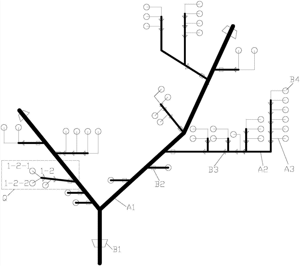
[0044] In each monitoring area, multiple water supply pipes are directly or indirectly connected to form a water supply network unit. The water supply network unit in each monitoring area has multiple water inlets and outlets; the water supply network units in each monitoring area are connected to each other through the corresponding water inlets and outlets to form a water supply network unit. Describe the urban water supply network,

[0045] Among the water supply pipes in each water supply network unit, the pipes directly connected to the two water inlets and outlets at both ends are the main pipe A1, which is directly branched from th...

Example

[0069] example 1:

[0070] Through system data monitoring, it is found that the net inflow of the monitoring area is 75 cubic meters per hour, and the total unit water volume data collected from the intelligent remote water meter B2 of each branch is 70 cubic meters per hour, and the water volume is unbalanced. , The calculation shows that the leakage rate of the main pipeline A1 is 6.6% exceeding the set warning leakage rate, so the main pipeline A1 is suspected of leakage and further leakage analysis is carried out; and then uploaded according to the branch intelligent remote water meter B2 To locate the leakage location of the main pipeline A1 where the leakage occurred, and finally assign the corresponding personnel to find the specific leakage point and take corresponding measures in time.

[0071] Example 2:

[0072] Through system data monitoring, it is found that the net inflow of the monitoring area is 80 cubic meters per hour, and the total unit water volume data collected...


PUM


Abstract

The invention relates to the technical field of pipe network leakage monitoring, in particular to a method and a monitoring system for establishing a multi-channel water supply structure leakage monitoring pipe network. The present invention includes step 1: delineate a plurality of different monitoring areas; step 2: divide metering nodes; step 3: connect all metering nodes in each monitoring area to the water supply network unit where they are located; step 4: provide Install smart remote water meters in the monitoring area; Step 5: Set up monitoring devices for each monitoring area to monitor pipeline leakage in the corresponding monitoring area; Step 6: Collect net inflow water data; Step 7: Sum and total of water consumption data Inflow water data are compared to determine whether there is water balance. The invention is used for finding the leakage situation of multi-way water inlet pipe network and locking the leakage position.

Description

technical field [0001] The invention relates to the technical field of pipe network leakage monitoring, in particular to a method and a monitoring system for establishing a multi-channel water supply structure leakage monitoring pipe network. Background technique [0002] The urban water supply network is an important infrastructure. With the development of the city, the urban water supply network system is becoming larger and more complex. In the process of use, the water supply pipe network often leaks due to some man-made or non-man-made factors, and many leaks are hidden and difficult to be discovered by people. If the leak is allowed to affect the health of residents Water is safe, and in the long run it will cause a great waste of water resources. [0003] However, in the face of the increasingly complex water supply pipe network system in today's society, the existing methods for monitoring leakage, especially in the case where there are multiple water supply plants ...

Claims


Application Information

Patent Timeline
IPC IPC(8): F17D5/02
CPCF17D5/02
Inventor 陈宏张惠益何玉真黄烈钱凌常陈赞标许为杰杨建萍龚兰珠
Owner 福水智联技术有限公司
Why Eureka
Try Eureka