
Self-righting aeronautical vehicle and method of use

a technology of aeronautical vehicles and frames, applied in the field of frames and apparatuses for frames and the construction of frames, can solve the problems of limited participation in the hobby, large structural damage to most models, and high cost of radio controls, so as to reduce the structural rigidity of vertical frames, minimize any supporting surface area, and maximum stability

Active Publication Date: 2018-10-30
ADVANCED AERODYNAMICS
View PDF22 Cites 16 Cited by
  • Summary
  • Abstract
  • Description
  • Claims
  • Application Information

AI Technical Summary

Benefits of technology

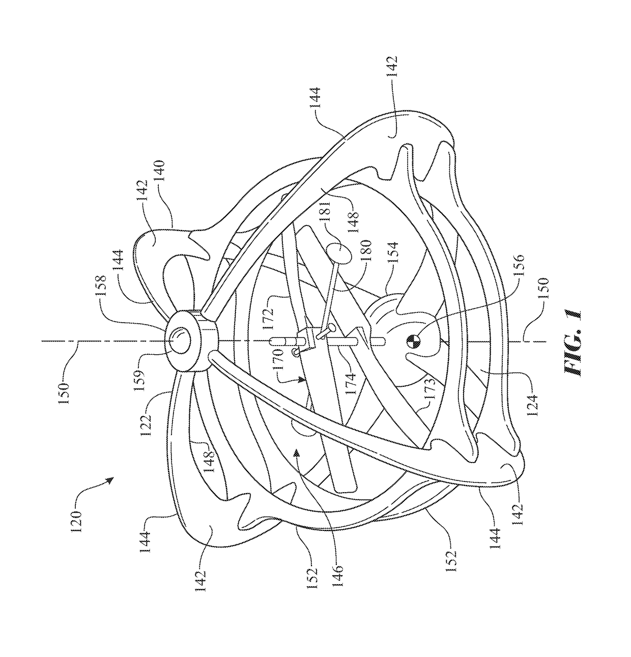
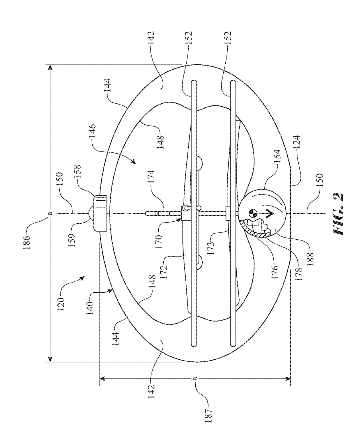
The self-righting frame assembly includes vertical frames and a horizontally oriented frame for maintaining a fixed spatial relationship with the vertical frames. A weighted mass is mounted within the frame assembly for positioning the center of gravity at the bottom. A protrusion is included to initiate the self-righting process when the frame assembly is placed in an inverted position on a supporting surface. The protrusion extends from the top of the vertical axis and above the vertical frames to displace the center of gravity beyond the point of contact with the vertical frame and produce a righting moment to return the frame assembly to an upright equilibrium position. The technical effect of this invention is to provide a frame assembly that can automatically right itself after being placed in an inverted position, without the need for external intervention.

Problems solved by technology

Initially, in the early years of RC aircraft popularity, the radio controls were relatively expensive and required a larger model aircraft to carry the weight of a battery, receiver and the various servos to provide the remote controllability for the model aircraft.
Consequently, these RC models represented a significant investment of the hobbyist's time, effort, experience, and money.
In the event of a crash, most models would incur significant structural damage requiring extensive repairs or even total rebuilding of the model.
For these reasons, participation in this hobby was self-restricting to the few who could make the required investments of time and money.
While the length of the required runways (even if only a relatively short grassy strip) vary according to the size of the RC model, the requirement often relegated the flying of these models to designated areas other than a typical back yard.
Flying a helicopter having a main rotor and a tail rotor requires a level of expertise that is significantly greater than required for a fixed wing aircraft, and therefore limits the number of hobbyists that can enjoy this activity.
These models typically have another limiting characteristic in that the form factor of the structure and the necessary placement of the rotors above the vehicle structure result in a tendency for the vehicle to be prone to tipping on one or the other side when landing.
Inspection of interiors of enclosed structures, such as piping, fuel tanks, water tanks, and the like can be a difficult task.
Automated equipment is unable to inspect vertically oriented surfaces.

Method used


Image

  • Self-righting aeronautical vehicle and method of use
  • Self-righting aeronautical vehicle and method of use
  • Self-righting aeronautical vehicle and method of use

Examples


Embodiment Construction

[0126]The following detailed description is merely exemplary in nature and is not intended to limit the described embodiments or the application and uses of the described embodiments. As used herein, the word “exemplary” or “illustrative” means “serving as an example, instance, or illustration.” Any implementation described herein as “exemplary” or “illustrative” is not necessarily to be construed as preferred or advantageous over other implementations. All of the implementations described below are exemplary implementations provided to enable persons skilled in the art to make or use the embodiments of the disclosure and are not intended to limit the scope of the disclosure, which is defined by the claims. For purposes of description herein, the terms “upper”, “lower”, “left”, “rear”, “right”, “front”, “vertical”, “horizontal”, and derivatives thereof shall relate to the invention as oriented in FIG. 1. Furthermore, there is no intention to be bound by any expressed or implied theo...


PUM


Abstract

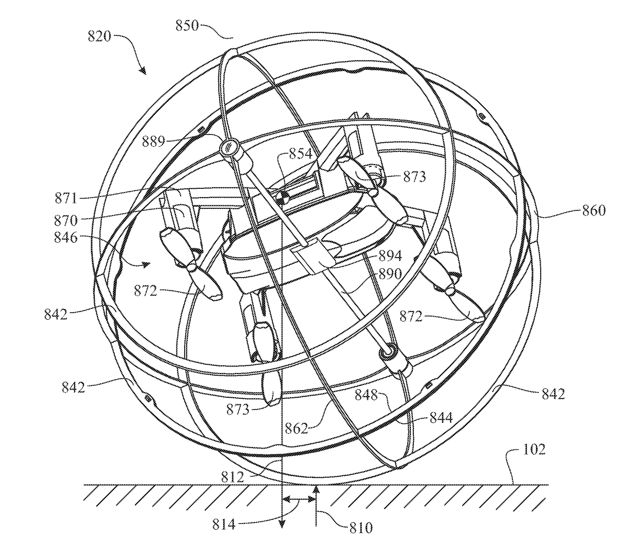
A self-righting aeronautical vehicle comprising a hollowed frame and a lift mechanism. The exterior of the frame and center of gravity are adapted to self-right the vehicle. The frame can include sealed, hollowed sections for use in bodies of water. The frame can be spherical in shape enabling inspection of internal surface of partially or fully enclosed structures. Inspection equipment can be integrated into the vehicle and acquired data can be stored or wirelessly communicated to a server. A controlled or other mass can be pivotally assembled to a pivot axle spanning across the interior of the frame. The pivot axis can rotate about a vertical axis (an axis perpendicular to the elongated axis). The propulsion mechanisms can be adapted for use as a terrestrial vehicle when enclosed in a sealed spherical shell.

Description

CROSS-REFERENCE TO RELATED APPLICATION[0001]This Non-Provisional Utility Patent Application is:[0002]a Continuation-In-Part Application (CIP) claiming the benefit of U.S. Non-Provisional patent application Ser. No. 15 / 257,904, filed on Sep. 6, 2016, scheduled to issue as U.S. Pat. No. 9,216,808 on Aug. 8, 2017,[0003]wherein U.S. Non-Provisional patent application Ser. No. 15 / 257,904 is a Continuation-In-Part Application (CIP) claiming the benefit of U.S. Non-Provisional patent application Ser. No. 14 / 977,546, filed on Dec. 21, 2015, now issued as U.S. Pat. No. 9,216,808 on Sep. 6, 2016,[0004]wherein U.S. Non-Provisional patent application Ser. No. 14 / 977,546 is a Divisional Application claiming the benefit of U.S. Non-Provisional patent application Ser. No. 14 / 751,104, filed on Jun. 25, 2015, now issued as U.S. Pat. No. 9,216,808 on Dec. 22, 2015,[0005]wherein U.S. Non-Provisional patent application Ser. No. 14 / 751,104 is a Divisional Application claiming the benefit of U.S. Non-Pro...

Claims


Application Information

Patent Timeline
Patent Type & Authority Patents(United States)
IPC IPC(8): B64C27/02B64C39/02B64D47/08G05D1/00A63H33/00B64C1/00B64C1/06B64C17/02A63H27/00A63H15/06B64C17/00B64C1/08A63H30/04B64C27/10
CPCB64C1/061A63H27/12A63H30/04A63H33/005B64C1/00B64C1/08B64C17/00B64C17/02B64C27/10B64C39/024B64D47/08G05D1/0011G05D1/0094A63H15/06B64C2201/146B64C2201/027B64C2201/108G05D1/0858B64C27/006B64C2203/00B64U2201/20B64U30/24B64U10/20B64U30/298B64U60/60B64U60/10B64U40/20B64U2101/26
Inventor YAN, GAOFEIDEES, JAMES
Owner ADVANCED AERODYNAMICS
Learn More