Offshore system

a technology of offshore system and drilling vessel, which is applied in the direction of pipe laying and repair, mechanical equipment, drilling pipes, etc., can solve the problems of high total running cost and only suitable drilling for common prior art vessels, and achieve the effect of reducing total running cos

Active Publication Date: 2012-03-27
ITREC BV
View PDF13 Cites 6 Cited by
  • Summary
  • Abstract
  • Description
  • Claims
  • Application Information

AI Technical Summary

Benefits of technology

[0007]The aim of the present invention is to propose an alternative and even more versatile offshore syst

Problems solved by technology

The main disadvantage of such a system is that such a drilling vessel that can only perform drilling operations is inefficient whe

Method used


Image

  • Offshore system
  • Offshore system
  • Offshore system

Examples


Embodiment Construction

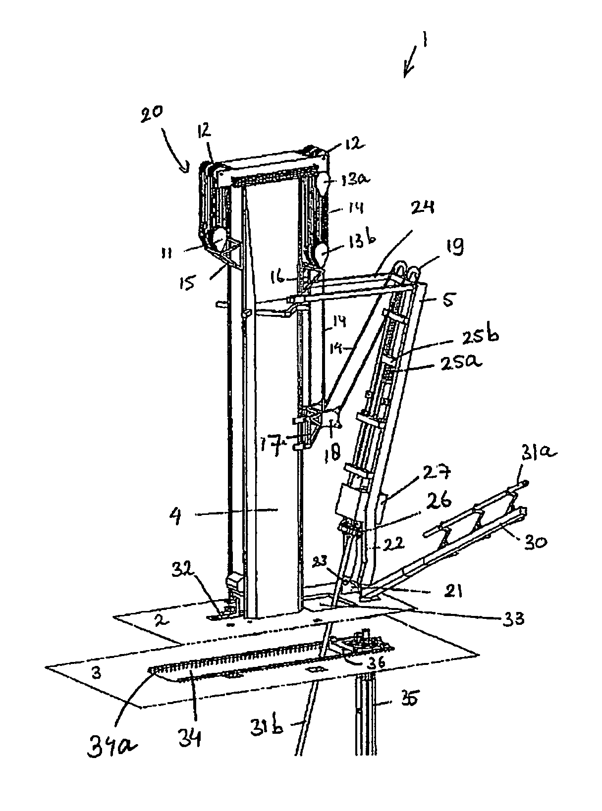
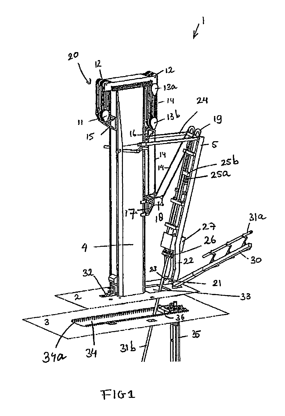
[0021]In FIG. 1 a schematic presentation of a possible embodiment of an offshore system 1 according to the invention is shown. From the vessel only part of an upper deck 2 and part of a lower deck 3 is shown. On the upper deck 2 a drilling tower 4, here a multipurpose tower is mounted. The tower is here embodied as a mast having an essentially closed outer wall. The mast here has a rectangular cross-section with an interior space allowing the internal arrangement of one or more winches and / or a heave compensation system. As an alternative tower a derrick could be used having a lattice structure as is well known in the art. Next to the multipurpose tower a tiltable J-lay tower 5 is mounted.

[0022]The multipurpose tower 4 comprises a hoist system 20 comprising blocks 11, pulleys 12 and in the shown embodiment a splittable block 13a and 13b for hoisting cables 14. It needs to be pointed out that although splittable blocks are the preferred embodiment also normal types of blocks can be u...


PUM


Abstract

This invention relates to an offshore system, comprising a drilling vessel, e.g. a semi-submersible drilling vessel comprising a deck on which a drilling tower for performing drilling operations is mounted. The vessel is furthermore provided with a support for a tiltable J-lay tower for laying a pipeline, said support being arranged next to the drilling tower, and the offshore system further includes a J-lay tower which is or can be mounted on said support.

Description

BACKGROUND OF THE INVENTION[0001]1. Field of the Invention:[0002]The invention relates to an offshore system, comprising a drilling vessel, e.g. a semi-submersible drilling vessel comprising a deck on which a drilling tower for performing drilling operations is mounted.[0003]2. Background of the Invention:[0004]Such an offshore system is well known and commonly used to perform drilling operations. The main disadvantage of such a system is that such a drilling vessel that can only perform drilling operations is inefficient when performing other operations and therefore has a high total running cost.[0005]It is known to overcome this drawback by replacing the drilling tower by a multipurpose tower, as described in U.S. Pat. No. 6,871,609. Such a multipurpose tower can be used to perform maintenance operations, as well as drilling operations. This increases the efficiency of an offshore system.[0006]In WO 2005 / 059297, WO 2004 / 020275, U.S. Pat. Nos. 6,932,553, 6,868,902, 6,763,898, 6,92...

Claims


Application Information

Patent Timeline
IPC IPC(8): F16L1/12
CPCE21B15/02F16L1/19
Inventor ROODENBURG, JOOPHAITSMA, JURJEN RINNERTCLAASSEN, LAURENS CORNELIS
Owner ITREC BV
Why Eureka
Try Eureka