
LED Lamp

a technology of led lamps and diodes, which is applied in the direction of lighting and heating apparatus, semiconductor devices for light sources, and lighting support devices. it can solve the problems of more power consumption, affecting the efficiency of lighting devices, and affecting the power consumption of devices, so as to achieve quick and easy assembly and disassembly

Active Publication Date: 2018-10-30
LIN RUEI HSING
View PDF13 Cites 2 Cited by
  • Summary
  • Abstract
  • Description
  • Claims
  • Application Information

AI Technical Summary

Benefits of technology

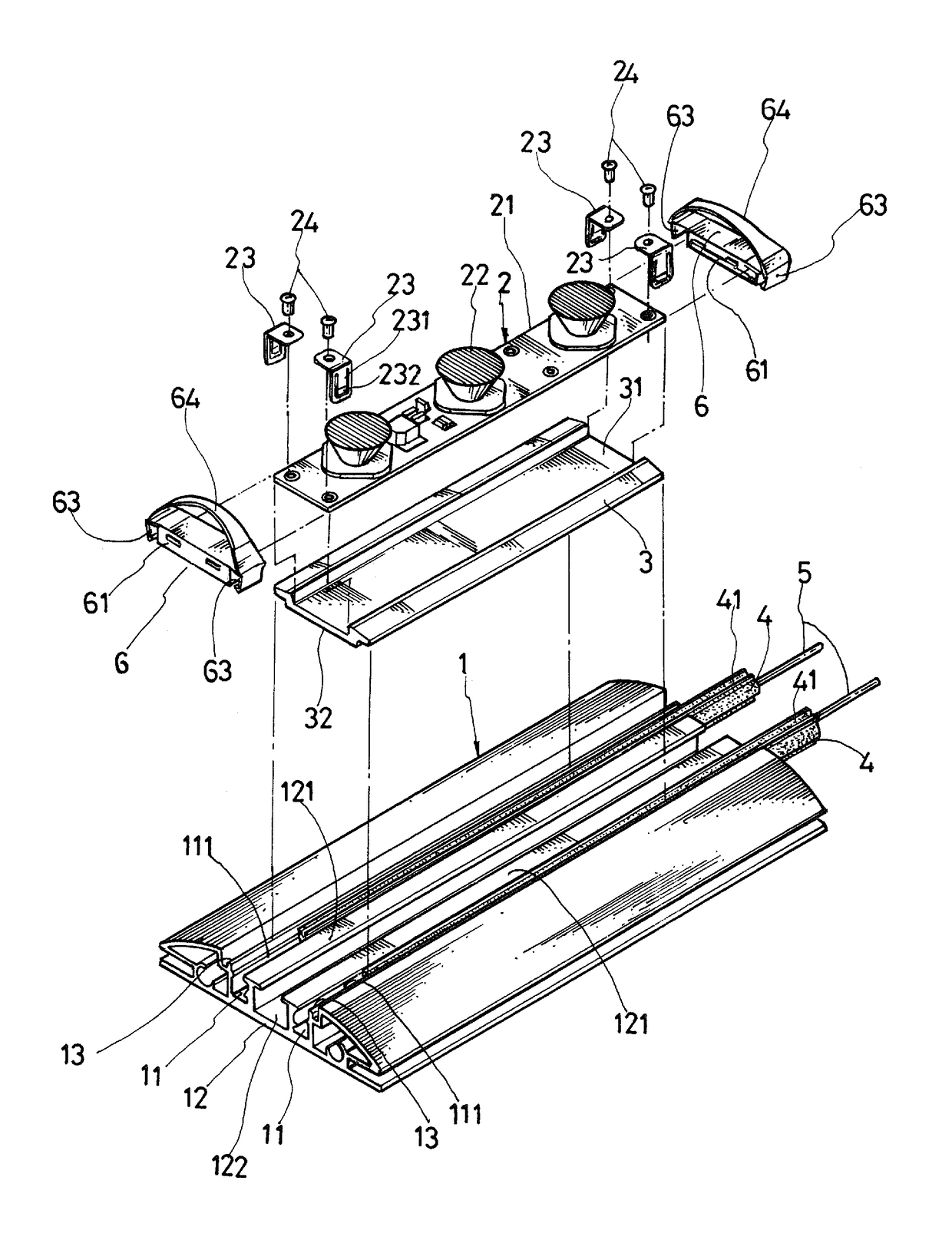
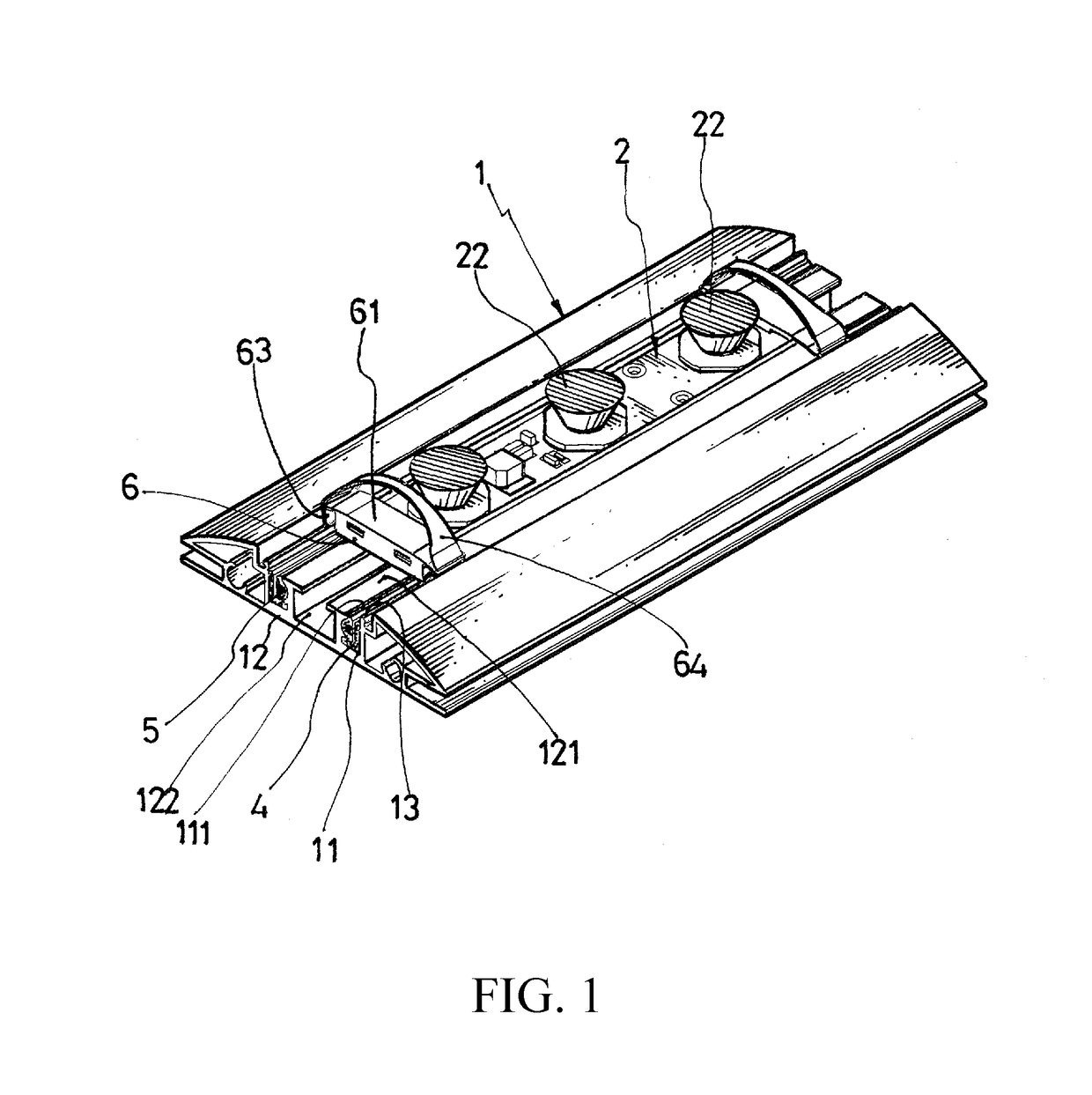
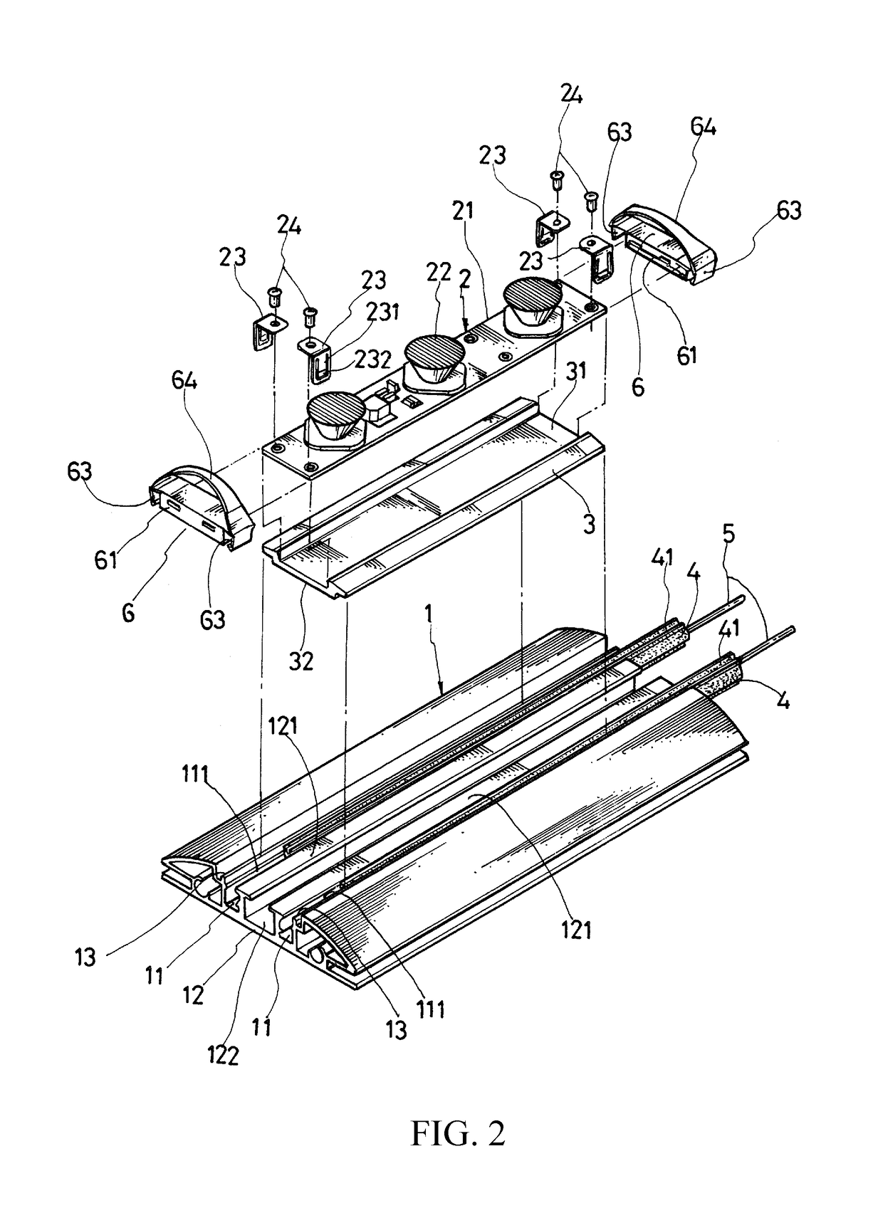
The present invention is about a LED lamp with easily assembled and disassembled positioning elements. The LED module and heat sinking piece are first plugged into the positioning elements, which are then embedded into the platform to securely hold the components. To disassemble, pulling the bands of the positioning elements expands the wedges outward, releasing them from the platform. This design allows for quick and easy assembly and disassembly of the LED lamp.

Problems solved by technology

Due to the recently increased awareness about environmental protection, carbon emission reduction, and energy conservation, the efficiency of lighting devices has become a key issue.
These devices' power consumption depends on the number of lighting device employed.
More light devices imply more power consumption.
In addition, for PL lamps and energy saving light bulbs, their operational lives and power consumption are still inferior to light emitting diodes (LEDs), despite their improved efficiency.
Furthermore, these lighting devices are all made of glass and suffer the potential hazard of explosion, especially when they are installed, recycled, and transportation.
Otherwise, the accumulated heat would have adversary effect to the LEDs' performance and operational life.
Existing heat sinking techniques, such as aluminum strips or plates, focus only on heat dissipation, and usually cannot be integrated into the electricity provision.
So far there is still no enhanced electricity provision mechanism for LED lamps.
For LED lamps with lengthy circuit boards, or when they are cascaded, the power attenuation problem has limit the applicability of LED lamps.
The existing provision mechanisms such as external connection, wire connection, all suffer problems such as difficulties and increased costs in installation and wiring.

Method used


Image

  • LED Lamp
  • LED Lamp
  • LED Lamp

Examples


Embodiment Construction

[0017]The following descriptions are exemplary embodiments only and are not intended to limit the scope, applicability or configuration of the invention in any way. Rather, the following description provides a convenient illustration for implementing exemplary embodiments of the invention. Various changes to the described embodiments may be made in the function and arrangement of the elements described without departing from the scope of the invention as set forth in the appended claims.

[0018]As shown in FIGS. 1 to 5, a light emitting diode (LED) lamp according to an embodiment of the present invention includes an aluminum platform 1, a LED module 2, a heat sinking piece 3, two insulating strips 4, two conductive wires 5, and two positioning elements 6.

[0019]The platform 1 has an elongated end-to-end indentation on a top major side, and has two top-open grooves 13 opposing each other in parallel along the indentation's top rims, and two ducts 11 opposing each other in parallel benea...


PUM


Abstract

The light emitting diode (LED) lamp includes an aluminum platform, a LED module, a heat sinking piece, two insulating strips, two conductive wires, and two positioning elements. The LED module and the heat sinking piece are mounted to the platform. Each conductive wire is embedded in the insulating strip and both are configured on the platform so that the LED module is electrically connected to the conductive wires. Each positioning element includes a connector portion for connecting an end of the LED module and the heat sinking element, two elastic arms extended downward from the positioning element's two ends, and an upwardly curved band whose two ends are connected to the two ends of the connector portion. Each elastic arm has a wedge at a bottom end for plugging into a groove of the platform. The LED lamp therefore provides quick and easy assembly and disassembly.

Description

BACKGROUND OF THE INVENTION(a) Technical Field of the Invention[0001]The present invention generally relates to light emitting diode (LED) lamps, and more particularly to a LED lamp with quick and easy assembly and disassembly.(b) Description of the Prior Art[0002]Due to the recently increased awareness about environmental protection, carbon emission reduction, and energy conservation, the efficiency of lighting devices has become a key issue. The most efficient light devices known today are fluorescent lamps, PL lamps, and energy saving light bulbs. These devices' power consumption depends on the number of lighting device employed. More light devices imply more power consumption. For example, four 20 W fluorescent lamps would consume 20 W×4=80 W. The same also applies to PL lamps and energy saving light bulbs. In addition, for PL lamps and energy saving light bulbs, their operational lives and power consumption are still inferior to light emitting diodes (LEDs), despite their impro...

Claims


Application Information

Patent Timeline
Patent Type & Authority Patents(United States)
IPC IPC(8): F21V29/83F21V19/00F21K9/20F21V23/00F21Y103/10F21Y115/10
CPCF21V19/0045F21V29/83F21K9/20F21V23/002F21Y2115/10F21Y2103/10F21V19/004F21V21/002F21V29/70
Inventor LIN, RUEI-HSING
Owner LIN RUEI HSING
Learn More