Drive control method and drive system operating according to said method

a technology of drive control and control method, which is applied in the direction of control system, electric motor control, electrical apparatus, etc., can solve the problems of only operating vibration sensors, damaging load torques, and endangering the gearbox, so as to prevent mill rumbling, simple intervention, and increase the effect of the rotation speed of the grinding tabl

Inactive Publication Date: 2018-11-06
SIEMENS AG
View PDF28 Cites 0 Cited by
  • Summary
  • Abstract
  • Description
  • Claims
  • Application Information

AI Technical Summary

Benefits of technology

[0020]The advantage of the invention is that, by varying the rotation speed of the grinding table, mill rumbling can be prevented without having to stop the grinding process, and that this result is achieved by comparatively simple intervention in the overall system, namely by controlling the electric motor.
[0021]For the rest, the rotating grinding table is only part of the mill conceivable as a vibration system. It is also alternatively or additionally possible—assuming that mill operation is not to be interrupted—for vibration system parameters other than the grinding table rotation speed to be influenced. For example, the material being ground on the grinding table is also part of the vibration system, so that by injecting water into the material being ground the properties thereof can be influenced. Alternatively or additionally, the grinding roller pressure can be influenced, as the grinding rollers are likewise part of the vibration system. Such influencing of the vibration system can also take place depending a pattern detected in the measured value characteristic.
[0022]Advantageous embodiments of the invention are set forth in the dependent claims. Back-references used in the dependent claims relate to further refinements of the subject matter of the main claim by virtue of the features of the particular dependent claim. They are not to be understood as a waiver of the right to independent, objective protection for the combination of features of the dependent claims to which they refer. In addition, having regard to an interpretation of the claims in the case of a more detailed concretization of a feature in a dependent claim, it is to be assumed that such a restriction does not exist in the respective preceding claims. Lastly it is pointed out that the method specified here can also be further developed according to the dependent device claims and vice versa.
[0023]If the electric motor is fed by a frequency converter, the rotation speed of the grinding table can be increased or reduced by the adjustment value by appropriately controlling the frequency converter. An alternative to a frequency converter is a superposition gear with which the above described varying of the rotation speed of the grinding table can be achieved in an essentially equivalent manner.
[0024]In one embodiment of the method, torque or speed measurements are used as vibration-relevant measured values and are acquired. The further description of the approach proposed here will be based, without loss of generality, on such torque or speed measurements. These will now be subsumed under the term measured values and a resulting torque or speed measured value characteristic is accordingly subsumed under the term measured value characteristic. To obtain such a measured value characteristic and the underlying measured values, a sensor system, i.e. at least one sensor incorporated in the sensor system or belonging to the sensor system, is used to measure a rotation speed of a rotating component of the drive train and / or at least one driving and / or supporting torque acting on the gearbox.
[0025]A corresponding embodiment of the drive system outlined above is characterized by such a sensor system for obtaining a vibration-relevant measured value in the form of a torque or speed measurement, wherein by means of the sensor system a rotation speed of a rotating component of the vertical roller mill and / or at least one driving and / or supporting torque acting in or on the gearbox can be measured and is measured during operation.

Problems solved by technology

However, experience has shown that such vibration sensors only operate with a certain time lag in response to an increase in the torque amplitudes in the drive.
By that time, damaging load torques may have come into play, possibly endangering the gearbox.
On the other hand, compensating for torque fluctuations does not necessarily also eliminate their cause, such as grinding bed undulation, for example.

Method used


Image

  • Drive control method and drive system operating according to said method
  • Drive control method and drive system operating according to said method
  • Drive control method and drive system operating according to said method

Examples


Embodiment Construction

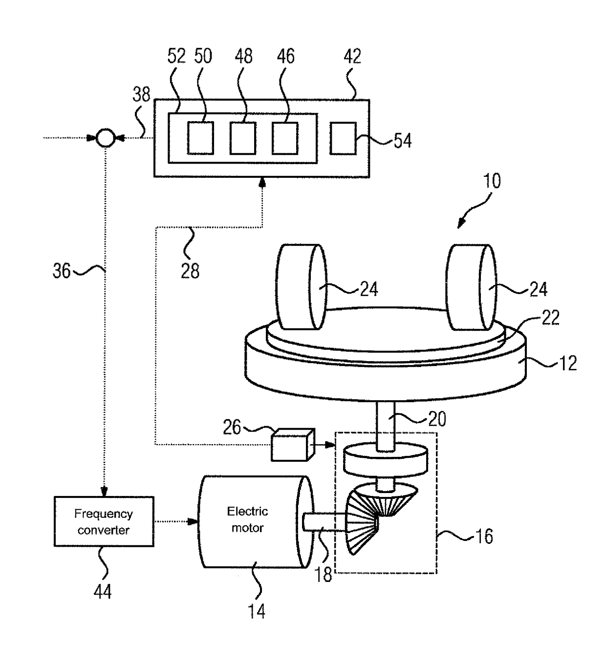
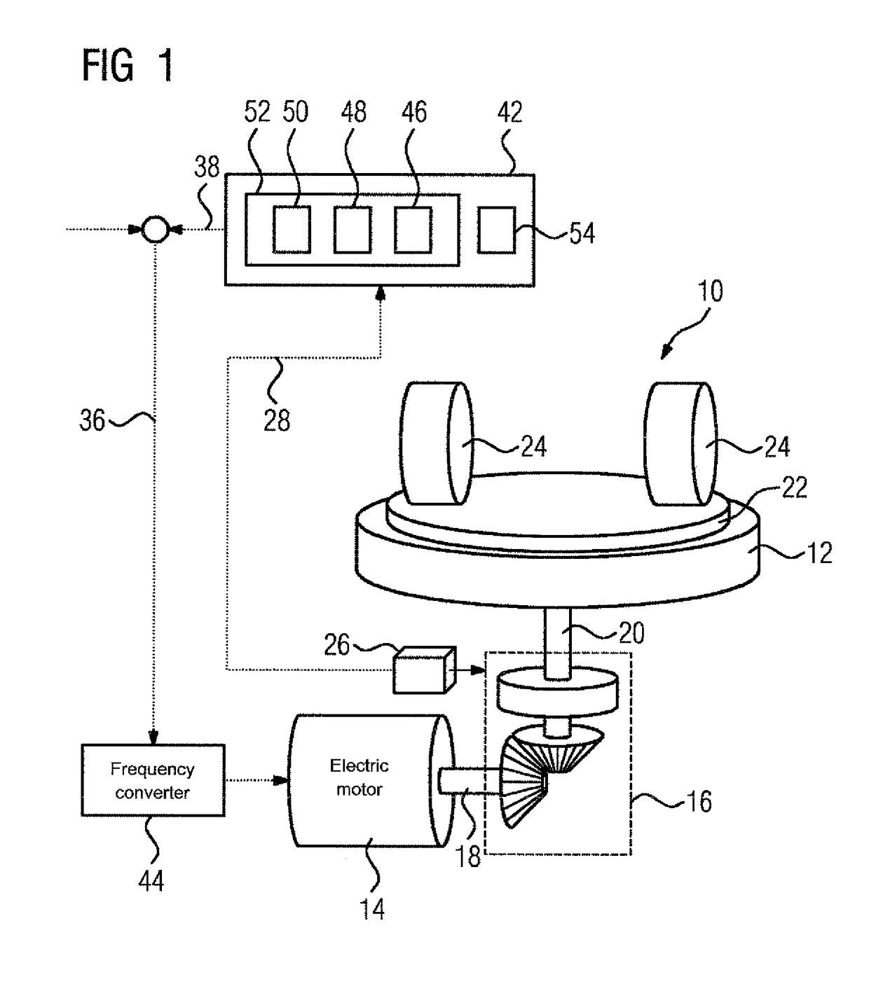
[0046]FIG. 1 shows a greatly simplified schematic representation of a vertical roller mill 10 for comminuting brittle materials, e.g. cement raw material. The vertical roller mill 10 comprises a grinding table 12 rotatable about the vertical. The grinding table 12 is driven by means of a heavy duty drive in the form of a motor, in particular an electric motor 14, and, in the example shown here, by means of a gearbox 16 located between electric motor 14 and grinding table 12. The gearbox 16 is shown here, without loss of further generality, as bevel-gear teeth with following planetary gearing not shown in greater detail. The gearbox 16 can also comprise spur-gear teeth or the like and / or a preceding or following planetary gearing or the like.

[0047]The vertical roller mill 10 comprises at least one driven shaft. In the illustration in FIG. 1, the vertical roller mill 10 comprises a motor shaft 18 and a grinding table shaft 20. All the means for transmitting the driving force of the el...


PUM


Abstract

A method for drive control of a vertical roller mill having a grinding table rotatable about a vertical axis includes driving the grinding table with a drive train comprising an electric motor and a gearbox with a rotation speed; monitoring a profile of a measured value derived from vibration-relevant measured values to detect a predefined pattern in the profile; and when the predefined pattern is detected, automatically increasing or reducing the rotation speed of the grinding table by a predefined adjustment value. A corresponding drive system operating according to the method is also disclosed.

Description

CROSS-REFERENCES TO RELATED APPLICATIONS[0001]This application is the U.S. National Stage of International Application No. PCT / EP2013 / 066483, filed Aug. 6, 2013, which designated the United States and has been published as International Publication No. WO 2014 / 111176 A1 and which claims the priority of German Patent Application, Serial No. 10 2013 200 578.4, filed Jan. 16, 2013, pursuant to 35 U.S.C. 119(a)-(d).BACKGROUND OF THE INVENTION[0002]The present invention relates to a drive control method, namely a method for controlling a heavy duty drive, in particular a heavy duty drive for a vertical roller mill for comminuting brittle materials such as cement raw material, and to a corresponding drive system operating according to said method.[0003]Vertical roller mills of the above mentioned type, having a grinding table rotating about the vertical and grinding rollers above the grinding table, are subject to severe mechanical vibrations. The resulting forces and torques can be so po...

Claims


Application Information

Patent Timeline
Patent Type & Authority Patents(United States)
IPC IPC(8): B02C25/00B02C15/00H02P31/00
CPCB02C25/00H02P31/00B02C15/007B02C15/02B02C2015/008B02C15/06
Inventor KUBE, ANDREAS
Owner SIEMENS AG
Why Eureka
Try Eureka