System and method for allowing restoration of first interconnection of die of power module

a power module and interconnection technology, applied in semiconductor/solid-state device testing/measurement, semiconductor devices, semiconductor device details, etc., can solve problems such as increasing cracks in various interface layers, power modules installed in applications that experience wear out, and inherent wearout in operation, so as to achieve simple intervention, increase the interconnection temperature, and restore the health of the power module

Active Publication Date: 2020-09-10
MITSUBISHI ELECTRIC CORP
View PDF0 Cites 0 Cited by
  • Summary
  • Abstract
  • Description
  • Claims
  • Application Information

AI Technical Summary

Benefits of technology

[0014]Thus, the health of the power module is able to be restored by a simple intervention.
[0015]In particular, micro-structure cracks in interconnections are targeted by the injection of high frequency current in order not only to increase the interconnection temperature, but also increase the pressure along these cracks and thereby increasing the rate of diffusion in this area. The diffusion causes the crack to heal, and therefore the lifetime of the power module is increased.

Problems solved by technology

Power modules installed in applications experience wear out due to the fact that they are composed of a variety of layered materials, each with different properties.
The wear out inherent to the operation manifests as an increasing crack in various interface layers such as the solder layer or the bond wires.
In order to combat wear out, power modules are designed with better matched materials, but this solution often suffers from poor electrical performance and higher manufacturing costs.
Furthermore, due to these additional manufacturing costs, it is not practical to design a power module to accommodate the most severe usage scenarios, leading to more stressful applications having lower power module lifetimes.
Typically, after a wear out failure has occurred, the power module is replaced requiring down time in the mission and added cost due to the necessary replacement of the power module.
In many applications, the cost of the down time and intervention and unpredictability of the power module failure is significant and can eliminate the benefit of using power electronics cost-wise entirely.
The weak point of power modules are the top side interconnections, which are subject to micro-structure cracks in the aluminium bond wires and / or the copper interconnections.

Method used


Image

  • System and method for allowing restoration of first interconnection of die of power module
  • System and method for allowing restoration of first interconnection of die of power module
  • System and method for allowing restoration of first interconnection of die of power module

Examples


Embodiment Construction

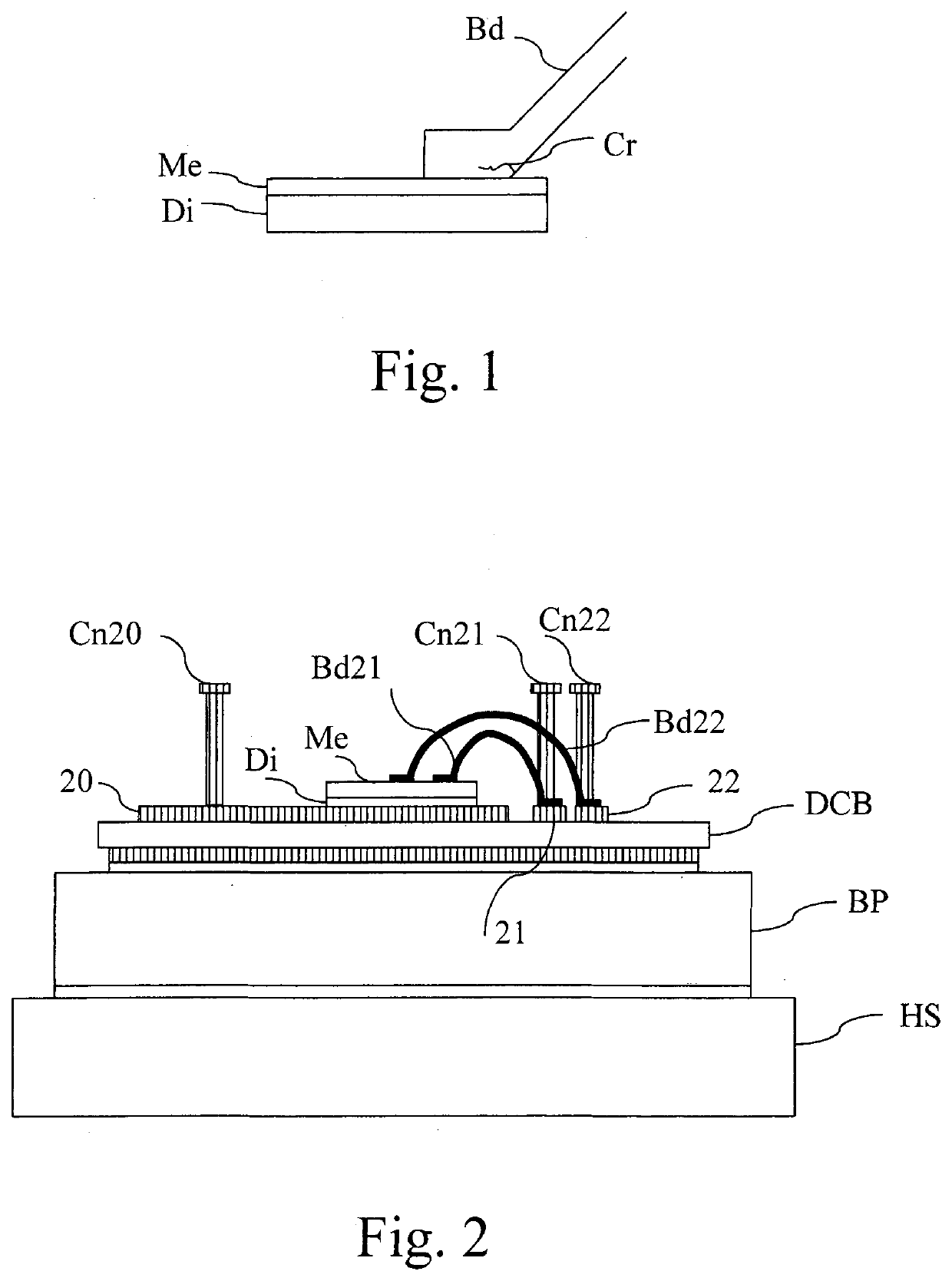
[0040]FIG. 1 represents an example of an aluminium bond wire top side interconnection of a power module.

[0041]The bond wire Bd is fixed on a Die Di via a metallization layer Me.

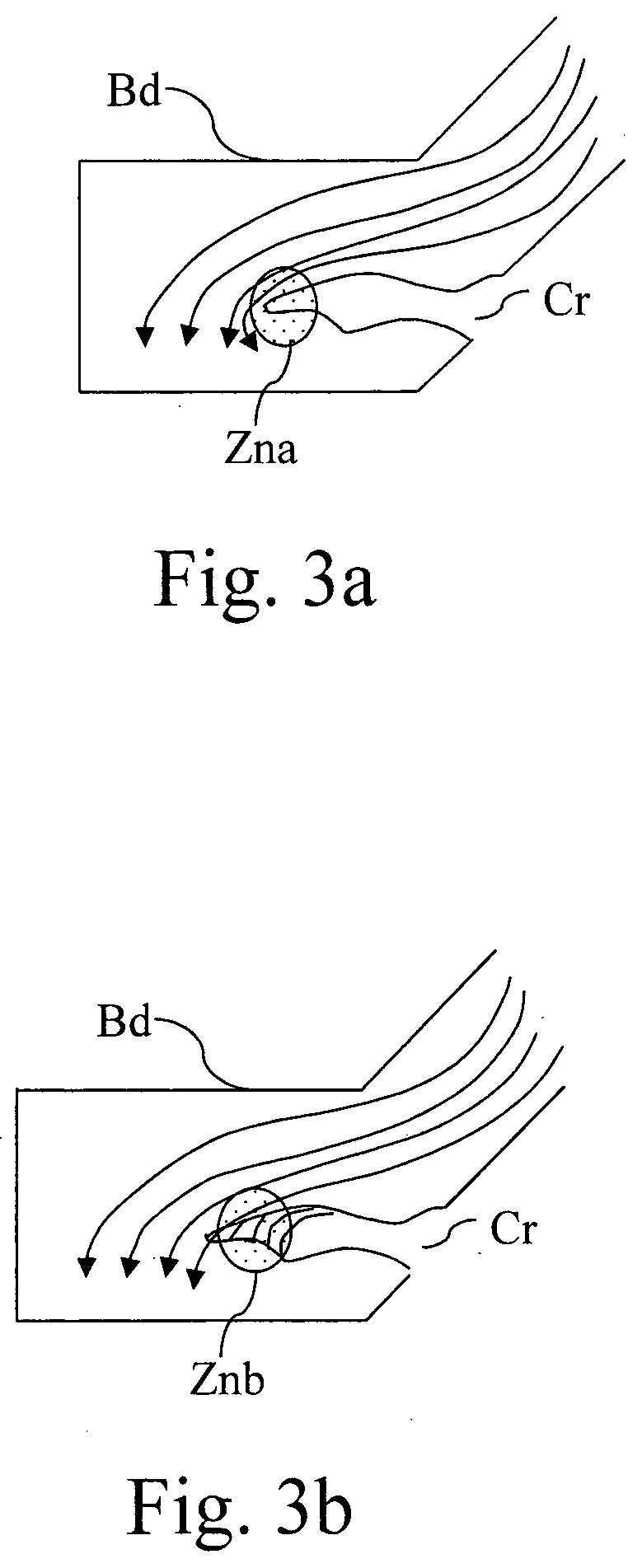
[0042]The bond wire Bd is subject to a micro-structure crack Cr. FIG. 2 represents a side view of a power module that has at least a supplementary connection that enables the present invention to be implemented.

[0043]A classical power module comprises top interconnections Cn20 and Cn21. The interconnections Cn20 and Cn21 are fixed respectively on copper layers 20 and 21 of a Direct copper bonding DCB which is fixed to a base plate BP and a heat sink HS.

[0044]The interconnection Cn21 and the copper layer 21 are connected to the die Di by a bond wire Bd21 that may be subject to micro-structure cracks.

[0045]According to the invention, the power module further comprises a supplementary interconnection Cn22 that is fixed on a copper layer 22 of the Direct copper bonding DCB. The interconnection Cn22, the copper la...


PUM


Abstract

The present invention concerns a system for allowing the restoration of a first interconnection of a die of a power module connecting the die to an electric circuit. The system comprises: at least one other interconnection of the power module, a periodic current source that is connected to the at least one other interconnection for generating a periodic current flow through the at least one other interconnection in order to reach, in at least a part of the first interconnection, a predetermined temperature during a predetermined time duration. The present invention concerns also the associated method.

Description

TECHNICAL FIELD[0001]The present invention relates generally to a device and a method and a system for allowing the restoration of an interconnection of a die of a power module.BACKGROUND ART[0002]Power modules installed in applications experience wear out due to the fact that they are composed of a variety of layered materials, each with different properties.[0003]Power modules have to support large temperature excursions during operation. The wear out inherent to the operation manifests as an increasing crack in various interface layers such as the solder layer or the bond wires.[0004]In order to combat wear out, power modules are designed with better matched materials, but this solution often suffers from poor electrical performance and higher manufacturing costs. Furthermore, due to these additional manufacturing costs, it is not practical to design a power module to accommodate the most severe usage scenarios, leading to more stressful applications having lower power module lif...

Claims


Application Information

Patent Timeline
Patent Type & Authority Applications(United States)
IPC IPC(8): H01L21/66H01L23/373H01L23/00
CPCH01L2924/19042H01L22/22H01L24/45H01L2224/215H01L2924/3512H01L23/3735H01L24/20H01L2924/19104H01L2224/45124H01L23/562H01L24/32H01L24/48H01L24/73H01L2224/32225H01L2224/45015H01L2224/48091H01L2224/48227H01L2224/48472H01L2224/73265H01L2924/00014H01L23/58H01L2924/00012H01L2924/01029H01L2924/01202H01L2224/05599H01L2224/29099H01L2924/2076
Inventor EWANCHUK, JEFFREYBRANDELERO, JULIOMOLLOV, STEFAN
Owner MITSUBISHI ELECTRIC CORP
Why Eureka
Try Eureka