Method for distributing a brake force, and braking device

a technology of brake force and braking device, which is applied in the direction of cycle brakes, cycle equipment, braking systems, etc., can solve the problems of unfavorable distribution of brake force on the front wheel and the rear wheel, delay in the response of the abs system, and hazardous situations, so as to improve the wear resistance of the brakes and tires, the effect of reducing the risk of injury and less wear

Active Publication Date: 2018-11-06
ROBERT BOSCH GMBH
View PDF29 Cites 1 Cited by
  • Summary
  • Abstract
  • Description
  • Claims
  • Application Information

AI Technical Summary

Benefits of technology

[0011]One advantage of the present invention is that the wear on the brakes and tires is optimized. A suitable distribution on the front wheel and rear wheel brakes distributes the brake forces better, so that overall less wear results. In particular, tire wear due to locking is also prevented. If an ABS system is additionally present which would intervene for an individual wheel, with the provided method it is often possible to avoid ABS intervention in many critical situations. A further advantage is that the braking distance is reduced due to the improved distribution of the brake forces on the front and rear wheels. Hazardous situations may be mitigated in this way.
[0013]In one specific embodiment of the method, the distribution of the total brake force is carried out based on stored information. This information may be stored in the brake pressure control device. This information preferably represents values of a table, or parameters of a function for ascertaining the distribution of the brake forces.
[0014]In another specific embodiment of the method, in the distribution of the total brake force, in addition to the information of the brake actuation detection means, information from additional sensors is taken into account in order to achieve an improved distribution of the brake forces. For example, the brake force may be distributed more heavily on the front wheel as a function of a braking acceleration or a downhill grade, or for an uphill grade more brake force may be distributed on a rear wheel. A hazardous situation, for example particularly high braking accelerations, high rotation rates, or a sharp reduction in speed may be recognized based on information from sensors. Based on the acceleration, it may also be determined whether the driver has a braking intent, for example when the driver decelerates the vehicle with the aid of the brake or other methods such as an engine brake or driving-related braking maneuvers. The particular driving situation a vehicle is in, for example whether it is negotiating a curve, may be taken into account in the distribution of the brake forces. For this purpose, the dynamics of the vehicle may be taken into account, for example by ascertaining the driving state based on information from sensors such as a rotation rate sensor and / or a speed sensor and / or an acceleration sensor. In principle, multiple signals of various sensors may be redundantly used for ascertaining the brake force distribution as well as for ascertaining a driving state of the vehicle.
[0015]The distribution of a total brake force on the front wheel and the rear wheel may include also changing the total brake force. For example, in a hazardous situation the total brake force may be significantly increased.
[0016]In another specific embodiment of the method, it is provided to divide the braking operation into multiple stages, each regarding the manner in which the brake pressure is influenced with the aid of the brake force influencing device. In a first stage, no intervention in the braking operation is made; i.e., the braking operation is carried out in the manner specified by the driver by his / her braking behavior. In a second stage, the brake pressure generated by the driver is slightly changed with the aid of the brake force influencing device. An average intensity of influencing takes place in the third stage, and a high intensity of influencing the brake pressure takes place in the fourth stage with the aid of the brake force influencing device. In a fifth stage, the brake pressure is held constant, regardless of which brake pressure the driver would like to effectuate, which represents the most intense influencing. The mentioned stages do not all have to be carried out in the method, and their sequence may also be arbitrary. In this way, the method may be adapted to the particular situation. Whether a hazardous situation or a normal braking situation is present in particular plays a role. The transition from a normal braking situation to a hazardous situation may be quantified and associated with the stages, so that the more hazardous an occurring situation is estimated to be, the more intense the influencing of the brake pressure that takes place. For example, the degree of hazard may be made a function of the intensity of the brake pressure which the driver generates by actuating the brake. Alternatively or additionally, information from additional sensors may be used for estimating the degree of hazard. It is possible, for example with the aid of a wheel motion sensor, to detect whether, and how intensely, a braking operation has been initiated. Alternatively or additionally, the actuation of a brake lever may be detected.

Problems solved by technology

This often results in an unfavorable distribution of the brake forces on the front wheel and the rear wheel.
The evaluation device classifies the situation as a hazardous situation when a brake pressure rises particularly sharply or rises once again in the course of a braking operation.
However, due to the improved distribution of the brake forces on the front and rear wheels, in many cases the response of an ABS system may be delayed compared to the generation of brake pressure by the driver.
The intervention into the braking system is thus limited to an improved distribution of the brake forces on the front and rear wheels.
This means that when there is a power failure, the brake forces generated by the driver are introduced into the distribution to the front and rear wheels in which the forces are generated by the driver.
The shut-off valves have a self-closing design, so that they interrupt the connection of the brake force influencing device to the braking system when a power failure is present.

Method used


Image

  • Method for distributing a brake force, and braking device
  • Method for distributing a brake force, and braking device
  • Method for distributing a brake force, and braking device

Examples


Embodiment Construction

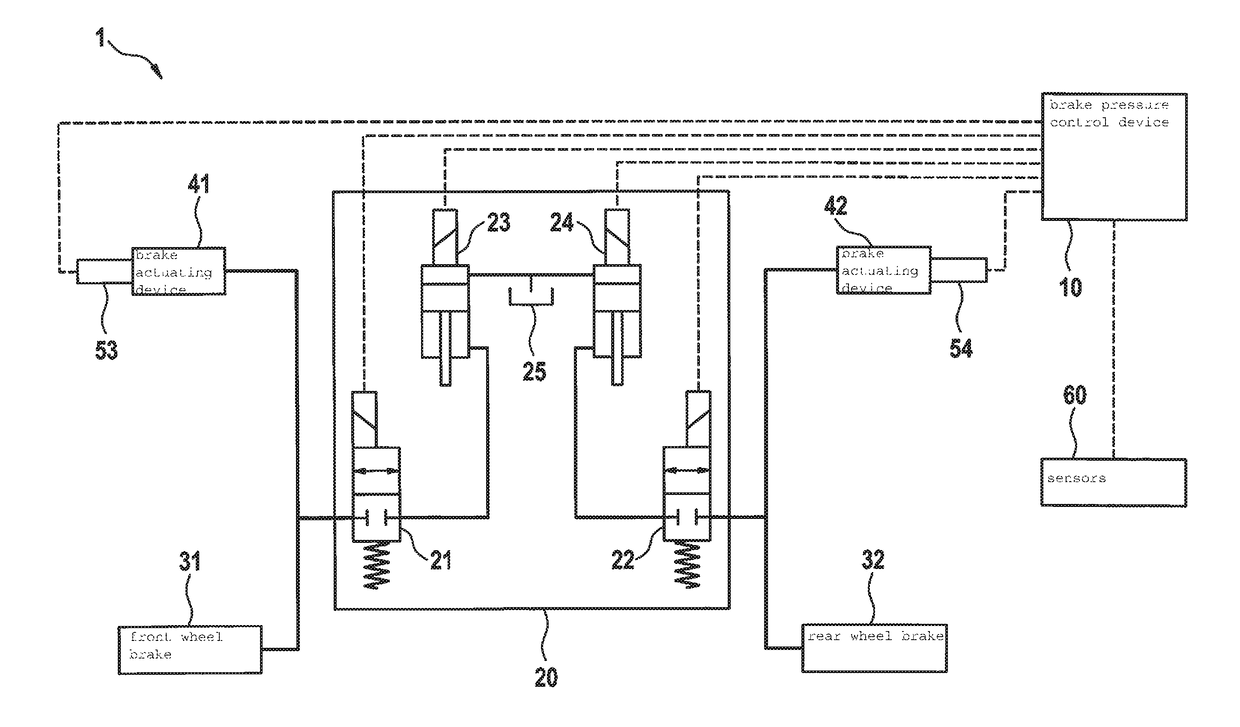
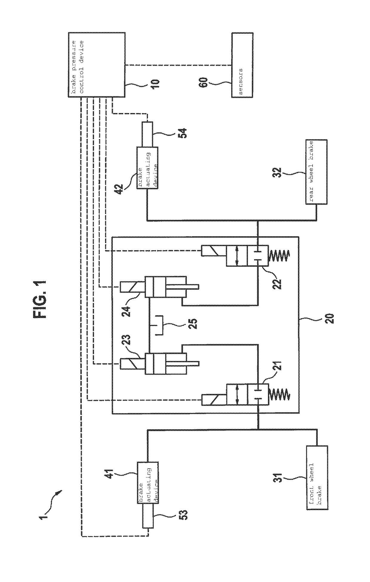
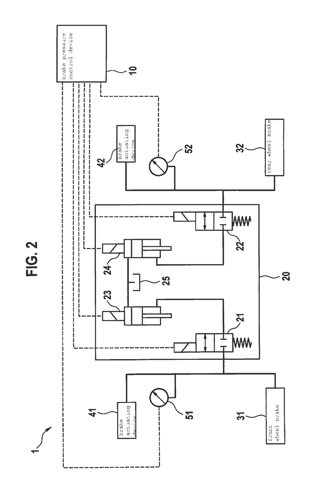
[0040]FIG. 1 shows a schematic illustration of a braking device 1 as a hydraulic-electrical circuit diagram. Braking device 1 includes a front wheel brake 31 and a rear wheel brake 32 which are each actuatable by a driver with the aid of a brake actuating device 41 and 42, respectively. Brake actuating devices 41, 42 are each designed as a hydraulic pressure generator which includes a cylinder and a piston. Brake actuating devices 41, 42 include a brake actuation measuring device 53, 54, respectively, as a brake actuation detector, which in the specific embodiment in FIG. 1 each generate a signal which corresponds to the relative position of the particular piston in the particular cylinder, or to a particular position of an actuating lever or an actuating pedal. The signals of brake actuation measuring device 53 or 54 are led to a brake pressure control device 10, which detects the extent of the actuation of front wheel brake 31 and of rear wheel brake 32. Brake pressure control dev...


PUM


Abstract

A method for braking a vehicle which is operable by a motor or by muscular power, in particular an electric bicycle. During a braking operation, a brake force influencing device is controlled by an electric brake pressure control device, and the brake pressure for the front wheel brake and / or for the rear wheel brake, and thus the brake force thereof, is increased and / or decreased. The brake pressure control device receives brake pressure signals in each case from a brake actuation detector for the front wheel brake and for the rear wheel brake, and an improved distribution of a total brake force on the front wheel and the rear wheel is effectuated which differs from the distribution that is effectuated by the driver.

Description

BACKGROUND INFORMATION[0001]The present invention relates to a method for braking a vehicle which is operable by a motor or by muscular power, in particular an electric bicycle. Such a vehicle includes a hydraulic front wheel brake and a hydraulic rear wheel brake, each of which is separately actuatable by a driver. The brake pressure effectuated at the front wheel brake or the rear wheel brake may be changed with the aid of an electrohydraulic brake force influencing device, in that the latter is controlled by an electrical brake pressure control device. The brake pressure at the front wheel brake and / or rear wheel brake, and thus also the brake force, may be increased and / or decreased in this way.[0002]In another aspect, the present invention relates to an electrohydraulic braking device which includes a hydraulic front wheel brake and a hydraulic rear wheel brake, as well as a separate brake actuating device for each of these two brakes. The braking device also includes an electr...

Claims


Application Information

Patent Timeline
Patent Type & Authority Patents(United States)
IPC IPC(8): B60T8/17B60T8/1766B60T13/16B60T8/42B62L3/02B60T8/171B60T8/34B62L3/08B60T8/26B60T8/32
CPCB60T8/261B60T8/171B60T8/1706B60T8/1766B62L3/08B60T8/341B60T8/4266B60T13/16B62L3/023B60T8/3225
Inventor DACKERMANN, TIMGREINER, RINALDO
Owner ROBERT BOSCH GMBH
Why Eureka
Try Eureka