Rotor positioning system in a pressure exchange vessel

a positioning system and pressure exchange vessel technology, applied in the direction of machines/engines, liquid fuel engines, positive displacement liquid engines, etc., can solve the problems of lack of true axial bearing stiffness and difficulty in manufactur

Active Publication Date: 2018-11-13
ISOBARIC STRATEGIES INC
View PDF9 Cites 16 Cited by
  • Summary
  • Abstract
  • Description
  • Claims
  • Application Information

AI Technical Summary

Problems solved by technology

Seawater is very corrosive with low viscosity leading to many challenges that demands the ultimate performance of materials, design and manufacturing.
This feature is difficult to manufacture as it prevents flatness to be addressed by precision lapping and also lacks any true axial bearing stiffness as it relies only on a weak hydrodynamic effect.

Method used


Image

  • Rotor positioning system in a pressure exchange vessel
  • Rotor positioning system in a pressure exchange vessel
  • Rotor positioning system in a pressure exchange vessel

Examples


Embodiment Construction

[0026]The following description is intended to convey a thorough understanding of the embodiments described by providing a number of specific embodiments and details involving rotor positioning system in a pressure exchange vessel. It should be appreciated, however, that the present invention is not limited to these specific embodiments and details, which are exemplary only. It is further understood that one possessing ordinary skill in the art, in light of known systems and methods, would appreciate the use of the invention for its intended purposes and benefits in any number of alternative embodiments, depending upon specific design and other needs.

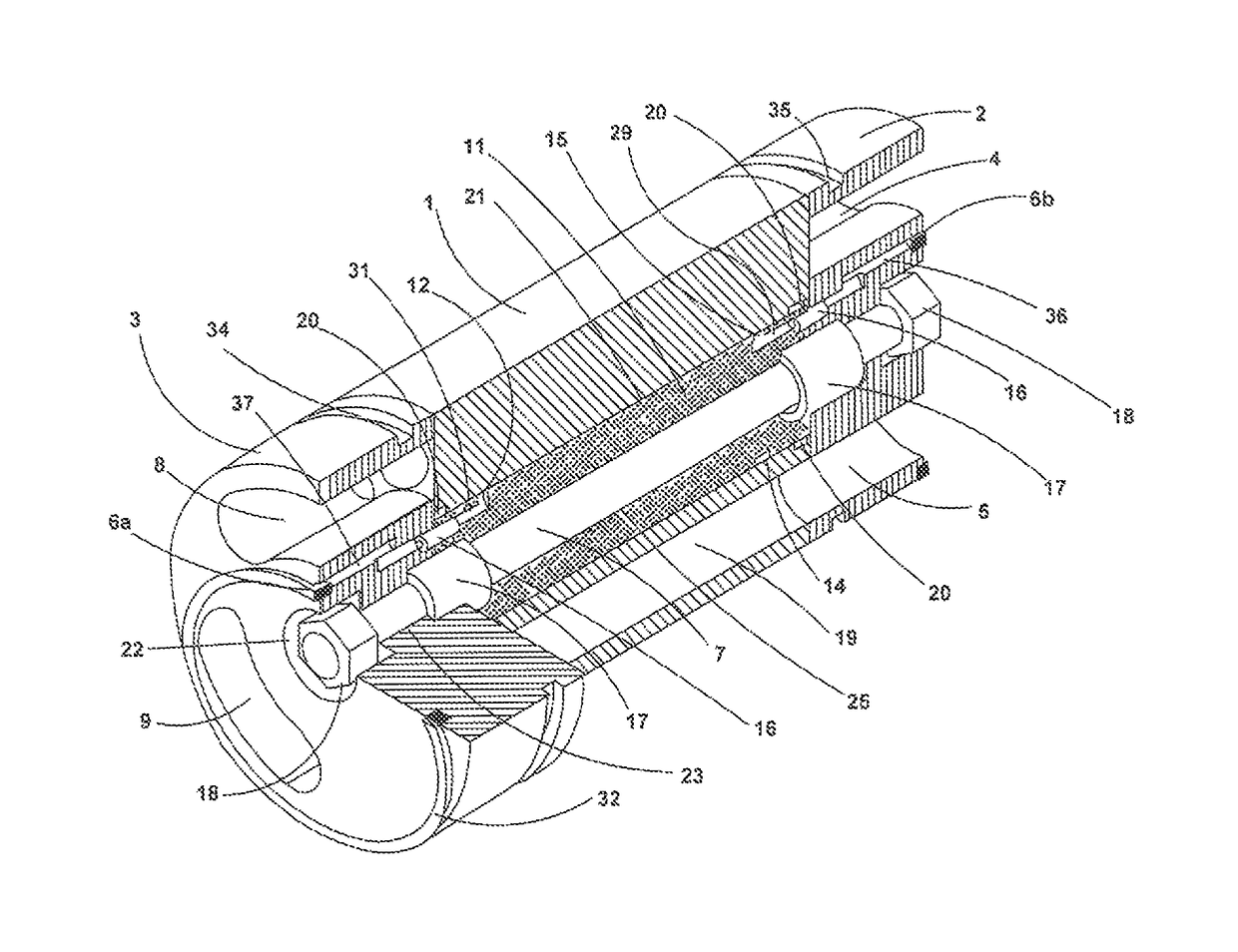
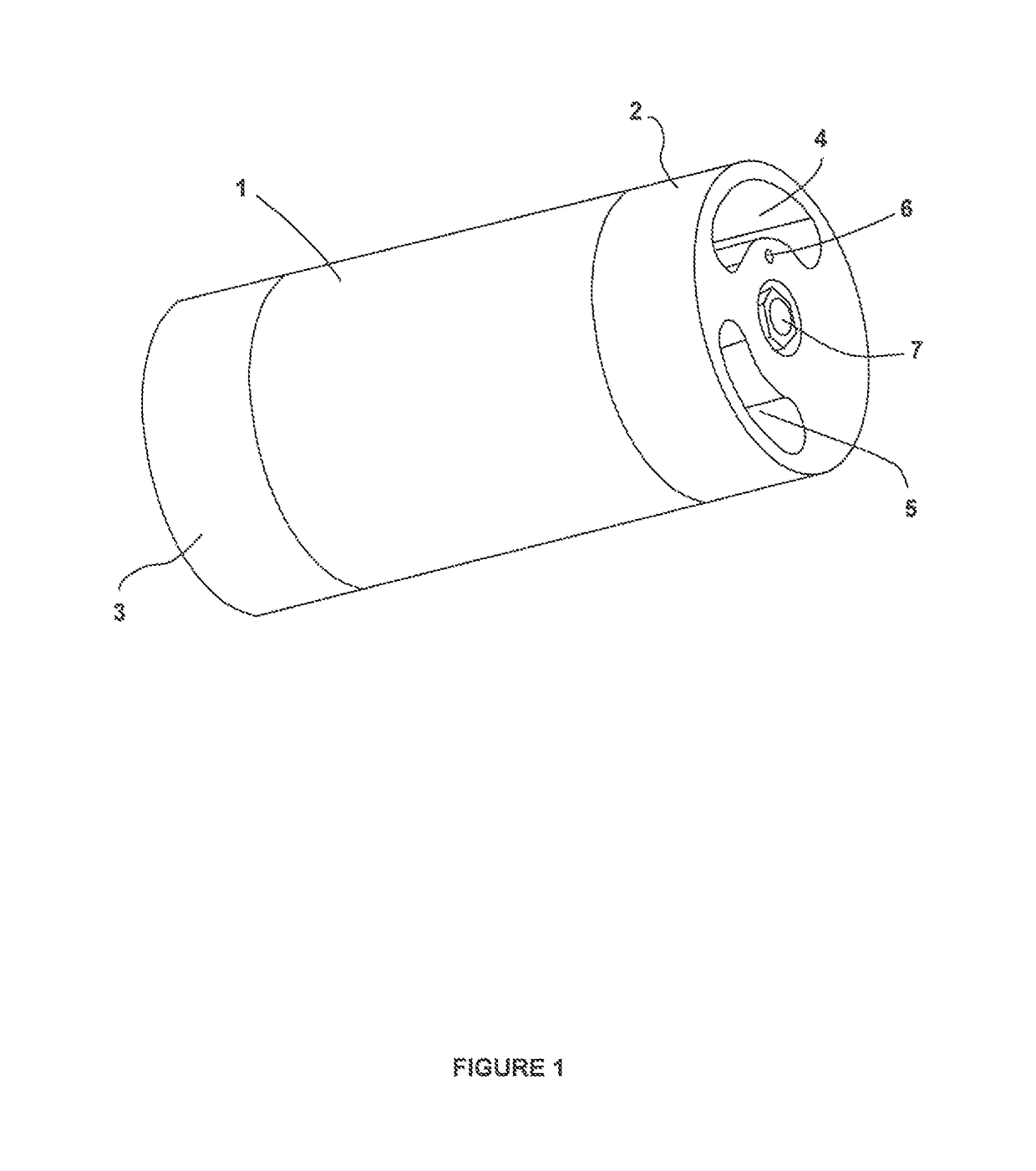
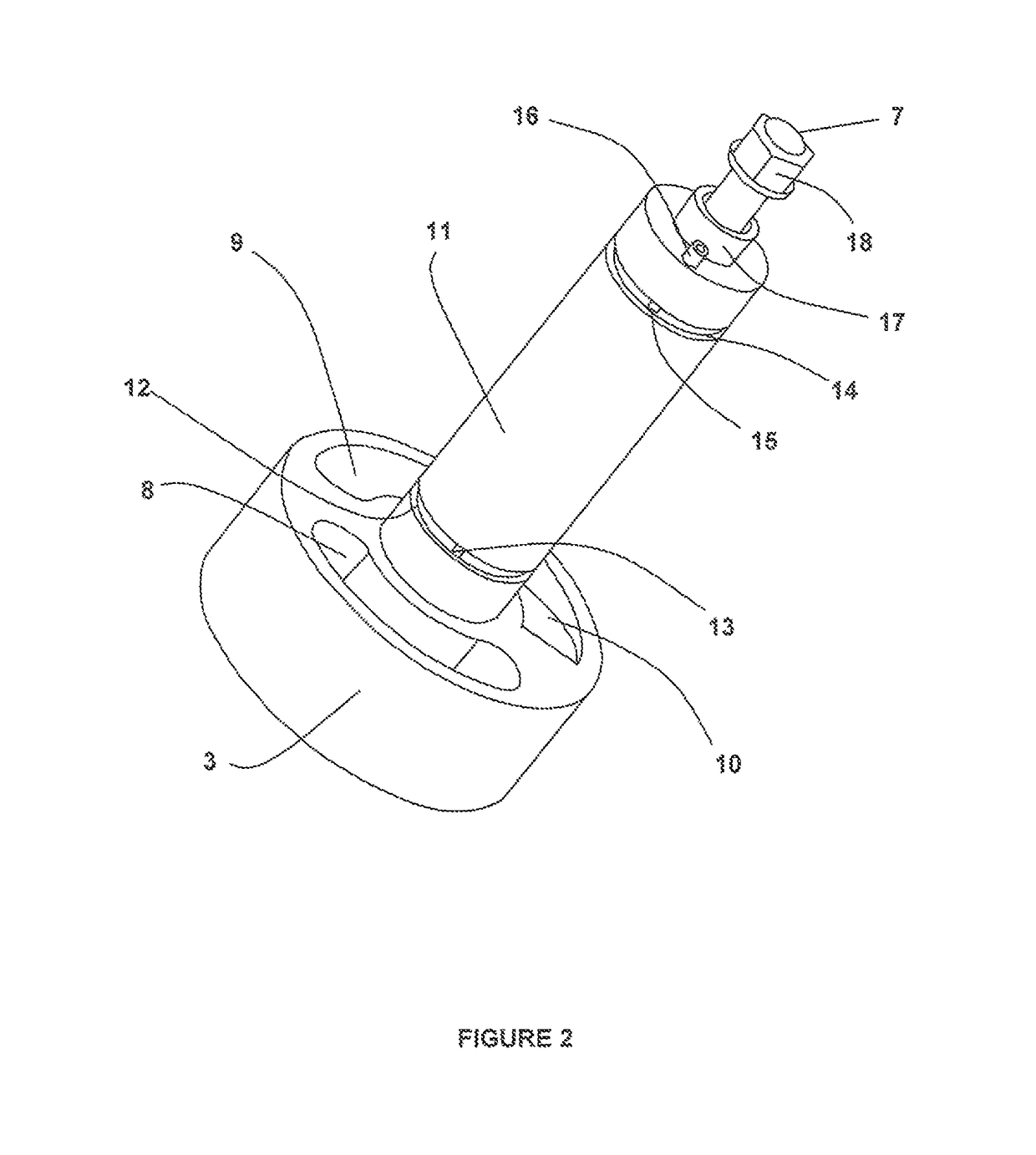
[0027]The present invention provides for a rotor positioning system for pressure exchangers using a central stationary axle. Hydrostatic bearing features on each end are separated by a hydrodynamic bearing surface. Each end of the axle contain a radial manifold directly connected to each high pressure fluid stream from where the fluid f...


PUM


Abstract

A rotor positioning system for rotary pressure exchangers with a rotor with a central bore accommodating an axle affixed to end covers in each end having at least one pair of high and low pressure ports in communication with opposing end cover ports through coaxial rotor ducts.

Description

CROSS-REFERENCE TO RELATED APPLICATIONS[0001]This patent application is a national stage application of International Patent Application No. PCT / US2014 / 034561, filed Apr. 17, 2014, which claims priority to U.S. Provisional Patent Application No. 61 / 813,125, filed Apr. 17, 2013, and U.S. Provisional Patent Application No. 61 / 847,829, filed Jul. 18, 2013, the disclosures of each of which are herein incorporated by reference.BACKGROUND INFORMATION[0002]The invention relates to a rotary pressure exchanger for transfer of pressure energy from one fluid to another by direct contact positive displacement. Such pressure exchangers are designed with a rotor being rotated by the fluid streams or by an external motor. The flow driven designs use either a sleeve or a central axle for positioning of the rotor between two pairs of end covers. The axle based pressure exchanger has the distinct advantage of being a very compact design as the rotor can be much larger within same size housing and acc...

Claims


Application Information

Patent Timeline
Patent Type & Authority Patents(United States)
IPC IPC(8): F04F13/00B01D61/06
CPCB01D61/06F04F13/00F04B1/2035F04B53/162F02B33/42
Inventor HAUGE, LEIF J.
Owner ISOBARIC STRATEGIES INC
Why Eureka
Try Eureka