Operation of a transmission device of a magnetic resonance device

a transmission device and magnetic resonance technology, applied in the direction of transmitter monitoring, transmission monitoring, instruments, etc., can solve the problems of inability of modulators in individual transmission paths to produce radiofrequency signals, change in phase differences between modulators, and high cost, and achieve the effect of low cost and easy operation

Active Publication Date: 2018-11-20
SIEMENS HEALTHCARE GMBH
View PDF26 Cites 0 Cited by
  • Summary
  • Abstract
  • Description
  • Claims
  • Application Information

AI Technical Summary

Benefits of technology

[0009]There are the following factors with respect to radiofrequency multichannel transmission systems that are desirable, for example, when applied to patients in magnetic resonance for increasing safety.
[0011]The transmitted radiofrequency signals (e.g., pulses) for each transmission path are intended to be detected with phase accuracy in relation to the reference plane of the transmission path. This is desirable, for example, with respect to the realtime monitoring of the transmitted pulses in order to be able to perform a disconnection in the event of a malfunction of a component in the transmission system. This, for example, prevents an excessively high local or global SAR entry into the patient or the like.
[0021]Apart from the connection of the external measuring device, all of the acts in the method according to one or more of the present embodiments may be performed automatically. For example, a user may be guided through the first calibration measurement by being provided with information with respect to the plug-in location to which the external measuring device is to be connected. The user, having connected the external measuring device, may confirm this. The measurements are performed automatically and, as a result, a new instruction for the next transmission path is output. In one embodiment, a dummy load may be connected downstream of the external measuring device (e.g., a 50Ω termination), which simulates an ideal coil element, and reflected components of the radiofrequency signal that is used for the calibration may be avoided.
[0022]One or more of the present embodiments therefore propose a calibration, monitoring and actuation method, with the aid of which the phase-accurate transmission and detection of radiofrequency pulses / radiofrequency signals in a multichannel radiofrequency transmission system may be provided. This has significance for the control of radiofrequency multichannel transmission systems in magnetic resonance devices and for monitoring the local SAR produced in the patient. The procedure described is independent of the radiofrequency coil used or of the coil elements used. The procedure may be realized for any desired number of transmission paths. In addition, the procedure may be realized easily and at low cost.
[0024]In one embodiment, the receiver that is associated with the external measuring device and, for example, is installed permanently in the transmission device may be used exclusively for the external measuring device. In order that the external measuring device is as independent as possible and is the same for each transmission channel, a special receiver is used for the external measuring device. The receiver is permanently associated with the external measuring device and may also be permanently installed in the transmission device, with the result that the measurement results may be passed on directly to a control device of the transmission device, and components to be connected manually may be reduced.

Problems solved by technology

In this case, there is the problem that the different modulators in the individual transmission paths may not produce radiofrequency signals in phase with one another.
The problem may also occur whereby the phase differences between the modulators change when the system is restarted.
Synchronization of the modulators may be provided, but is technically extremely complex.

Method used


Image

  • Operation of a transmission device of a magnetic resonance device
  • Operation of a transmission device of a magnetic resonance device

Examples


Embodiment Construction

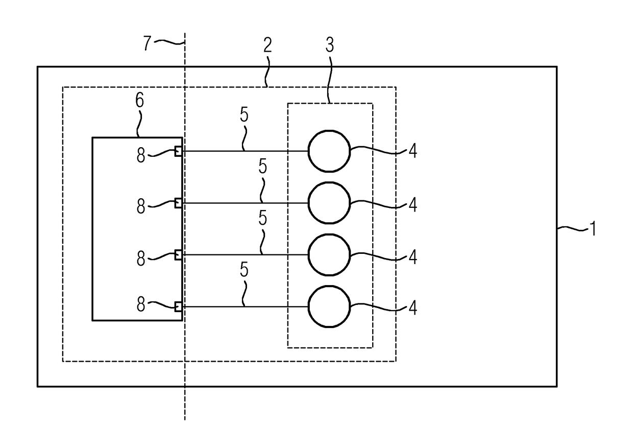
[0036]FIG. 1 shows one embodiment of a magnetic resonance device 1 that, as is not illustrated in more detail here for reasons of clarity, includes components that are conventional in the prior art. For example, a main magnet unit includes a superconducting main magnet. The main magnet unit defines a patient area, into which a patient couch may be inserted. In addition, a gradient coil arrangement is provided surrounding the patient area.

[0037]Radiofrequency signals for exciting the nuclear spins are generated by a radiofrequency multichannel transmission system 2 in the magnetic resonance device 1. The radiofrequency multichannel transmission system includes a radiofrequency coil 3 (e.g., a body coil that includes a plurality of independently actuatable coil elements 4). In one embodiment, with knowledge of the magnetic fields (e.g., may be measured and stored as B1 maps) produced by the individual coil elements 4, any desired excitations may be produced (e.g., the coil elements 4 ...


PUM


Abstract

A method for operating a transmission device of a magnetic resonance device is provided. In order to actuate coil elements of a radiofrequency coil with different phases, phase differences in a reference plane are taken into consideration. In a first calibration measurement to be performed once for each transmission path, a first phase of a transmitted radiofrequency signal is measured by an internal measuring device installed permanently in the transmission device spaced apart from the reference plane. A second phase of the transmitted radiofrequency signal is measured by a second, external measuring device to be connected to the reference plane for the first calibration measurement. At least one phase of the first phase and the second phase is taken into consideration in the phase-accurate actuating of the coil elements and / or for correcting further measurements with the internal measuring device.

Description

[0001]This application claims the benefit of DE 10 2013 206 570.1, filed on Apr. 12, 2013, which is hereby incorporated by reference.BACKGROUND[0002]The present embodiments relate to operation of a transmission device of a magnetic resonance device.[0003]In magnetic resonance imaging, it has been proposed to configure transmission coils (e.g., radiofrequency coils) such that the transmission coils include different coil elements that may be actuated independently of one another. If it is known which magnetic fields are produced by which coil element, different excitation patterns in the imaging range may thus be produced (e.g., volume-selective excitations or the like). For this purpose and also in order to compensate for lighter or darker points in images as a result of reflections, for example, or the like, provision may be made for defined phase differences between the individual channels defined by transmission paths to be produced in order to realize interferences.[0004]In orde...

Claims


Application Information

Patent Timeline
Patent Type & Authority Patents(United States)
IPC IPC(8): H04B17/00G01R33/36H04B17/12G01R33/561G01R33/58
CPCG01R33/3607H04B17/12G01R33/586G01R33/5612
Inventor ADOLF, HOLGERBENNER, THOMASFAUTZ, HANS-PETERFONTIUS, JOERG ULRICHGUMBRECHT, RENE
Owner SIEMENS HEALTHCARE GMBH
Why Eureka
Try Eureka