Solid-state lighting with auto-select settings for line voltage and ballast voltage

a solid-state lighting and auto-selecting technology, applied in the field of led lamps, can solve the problems of high total cost of ownership, incompatibility between identifying ballasts and replacing, and high cost of replacement of ballasts, so as to reduce the risk of lamp damage, without ambiguity and risk of internal fir

Active Publication Date: 2018-11-20
ALEDDRA INC
View PDF5 Cites 1 Cited by
  • Summary
  • Abstract
  • Description
  • Claims
  • Application Information

AI Technical Summary

Benefits of technology

[0008]A light-emitting diode (LED) lamp comprising a first full-wave rectifier, a ballast operation circuit, an LED driving circuit, one or more LED arrays, and an optocoupler, is used to replace a fluorescent tube or a conventional LED tube lamp in lamp fixture sockets wired to connect to either AC mains or a ballast. The ballast operation circuit comprising two frequency sensitive devices, a second full-wave rectifier, and two or more diodes connected in series, is configured to auto-select an input AC voltage to operate the LED lamp without ambiguity and risk of internal fire. When the input AC voltage is from the ballast, the optocoupler is enabled to disable the LED driving circuit whereas the one or more LED arrays are powered by the second full-wave rectifier. When the input AC voltage is from the AC mains, the optocoupler is disabled to maneuver the LED driving circuit whereas the one or more LED arrays are powered by the LED driving circuit, pre-powered by the first full-wave rectifier. The scheme can effectively reduce a risk of lamp damages due to misapplications.
[0010]The optocoupler comprises an infrared emitting diode and a phototransistor and is configured to operate in response to the second DC voltage and to disable the LED driving circuit when enabled. The two or more diodes connected in series in the ballast operation circuit are connected between the LED Arrays and the second full-wave rectifier. When the input AC voltage is from the ballast, the two or more diodes connected in series build up a forward bias voltage across the infrared emitting diode in the optocoupler, operating the optocoupler. In other words, the forward bias voltage enables the infrared emitting diode to optically couple an “on” signal to the phototransistor, which is connected in series between a relatively high voltage potential and a relatively low voltage potential of the power sustaining device. The “on” signal coupled to the phototransistor results in electric current conduction, which pulls down the relatively high voltage potential of the power sustaining device to the relatively low voltage potential. Without power in the power sustaining device to sustain operation of the LED driving circuit, the LED driving circuit is disabled. The two or more diodes connected in series allow an electric current flow only in a direction from the one or more LED arrays to a low DC potential port of the second full-wave rectifier to ensure to build up the forward bias voltage higher than a forward voltage of the infrared emitting diode, thereby promoting a forward current flow in the infrared emitting diode while permitting different electrical potentials between the infrared emitting diode and the phototransistor. To improve lamp compatibility with various ballasts: instant-start, rapid-start, and program-start, the first full-wave rectifier and the input filter are so connected to form an electric current path configured to allow an initial current passing thereon and returning back to various ballasts so that the various ballasts can subsequently generate a high input AC voltage to operate the second full-wave rectifier and further to power the one or more LED arrays.

Problems solved by technology

But the fact is that total cost of ownership for this approach is high regardless of very low initial cost.
If the existing ballast is not compatible with the ballast-compatible LED lamp, the consumer will have to replace the ballast.
Some facilities built long time ago incorporate different types of fixtures, which requires extensive labor for both identifying ballasts and replacing incompatible ones.
Maintenance will be complicated, sometimes for the lamps and sometimes for the ballasts.
The labor costs and long-term maintenance costs will be unacceptable to end users.
In this sense, any energy saved while using the ballast-compatible LED lamps becomes meaningless with the constant energy use by the ballast.
In the long run, the ballast-compatible LED lamps are more expensive and less efficient than self-sustaining AC mains-operable LED lamps.
In some prior art schemes, a switching mode power supply (SMPS) type LED driver is proposed to use with a ballast, but has not been completely accepted due to occasional fires that arise inside the ballast.
The cause of these fires has been identified to be a large direct-current (DC) input capacitor in the SMPS type LED driver, which may destroy a capacitor in the ballast due to excessive initial resonant voltage.
Such a Buck converter is controlled by a control logic, which has several drawbacks that limit its use in ballast applications.
First, the control logic has a low operating voltage range which inherently limits the wide range of input voltages that can be used.
Third, the Buck converter operates in a continuous conduction mode, in which an input current fails to follow the input voltage, leading to a low power factor with the AC mains and turn-on or other operational failures with the ballast.
When the input voltage drops to the minimum operating voltage level, the control logic fails to operate and sends no signals to the switch, and the Buck converter stops to function until the input voltage level recovers, resulting in flickering.
In the worst case, an LED lamp that is designed for a group of three or four lamps in a fixture powered by a ballast may be burned out due to over-rated current flowing into the LED arrays in the lamp if only one of such a lamp is installed and operated for a long time in the fixture.
For the latter case, the output voltage control approach may work with an electronic ballast but cannot be used in AC mains.
In general, conventional LED drivers fail to work with a ballast and to properly operate an LED lamp at a regulated power, resulting in unstable lighting output.
Without power in the power sustaining device to sustain operation of the LED driving circuit, the LED driving circuit is disabled.

Method used


Image

  • Solid-state lighting with auto-select settings for line voltage and ballast voltage
  • Solid-state lighting with auto-select settings for line voltage and ballast voltage
  • Solid-state lighting with auto-select settings for line voltage and ballast voltage

Examples


Embodiment Construction

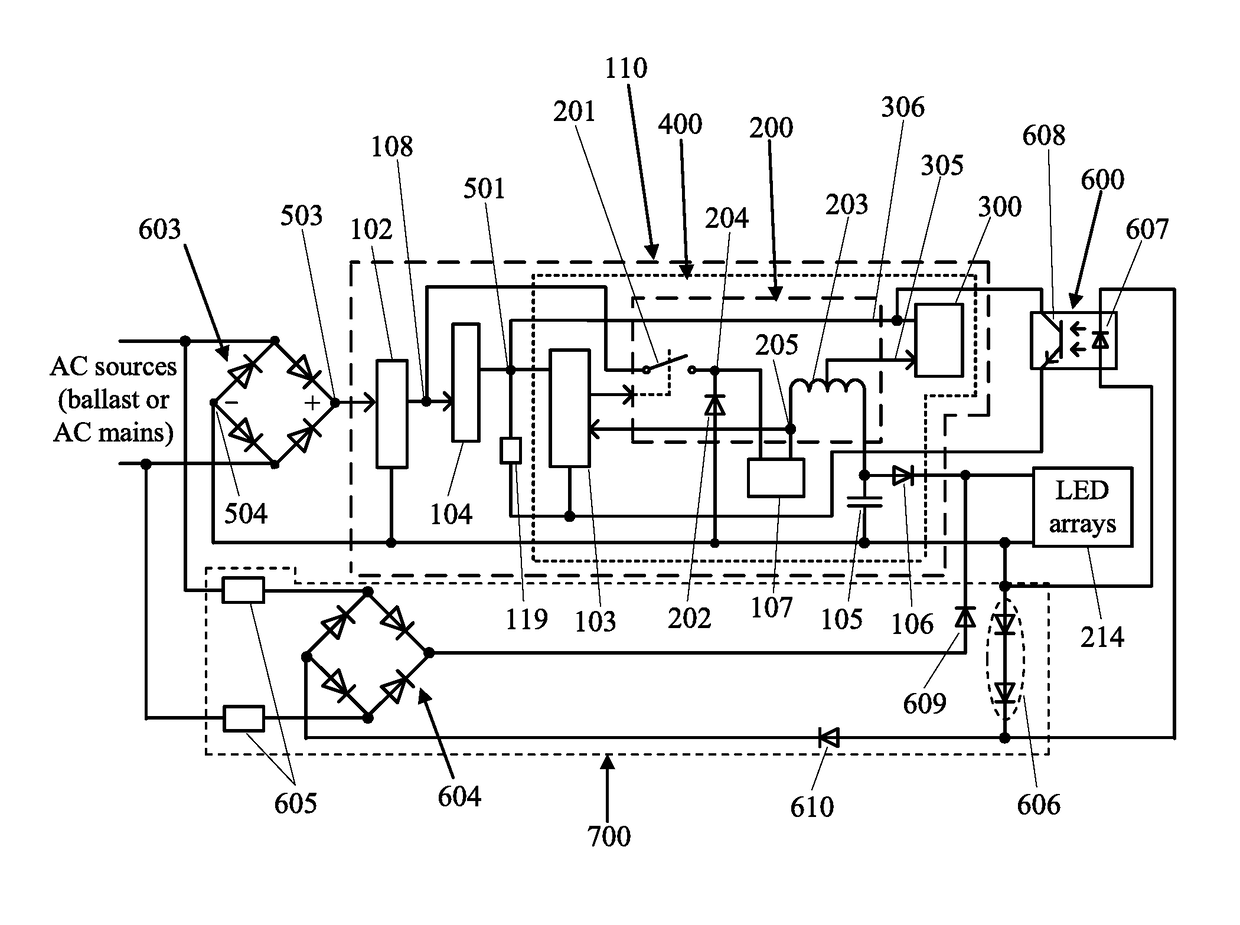
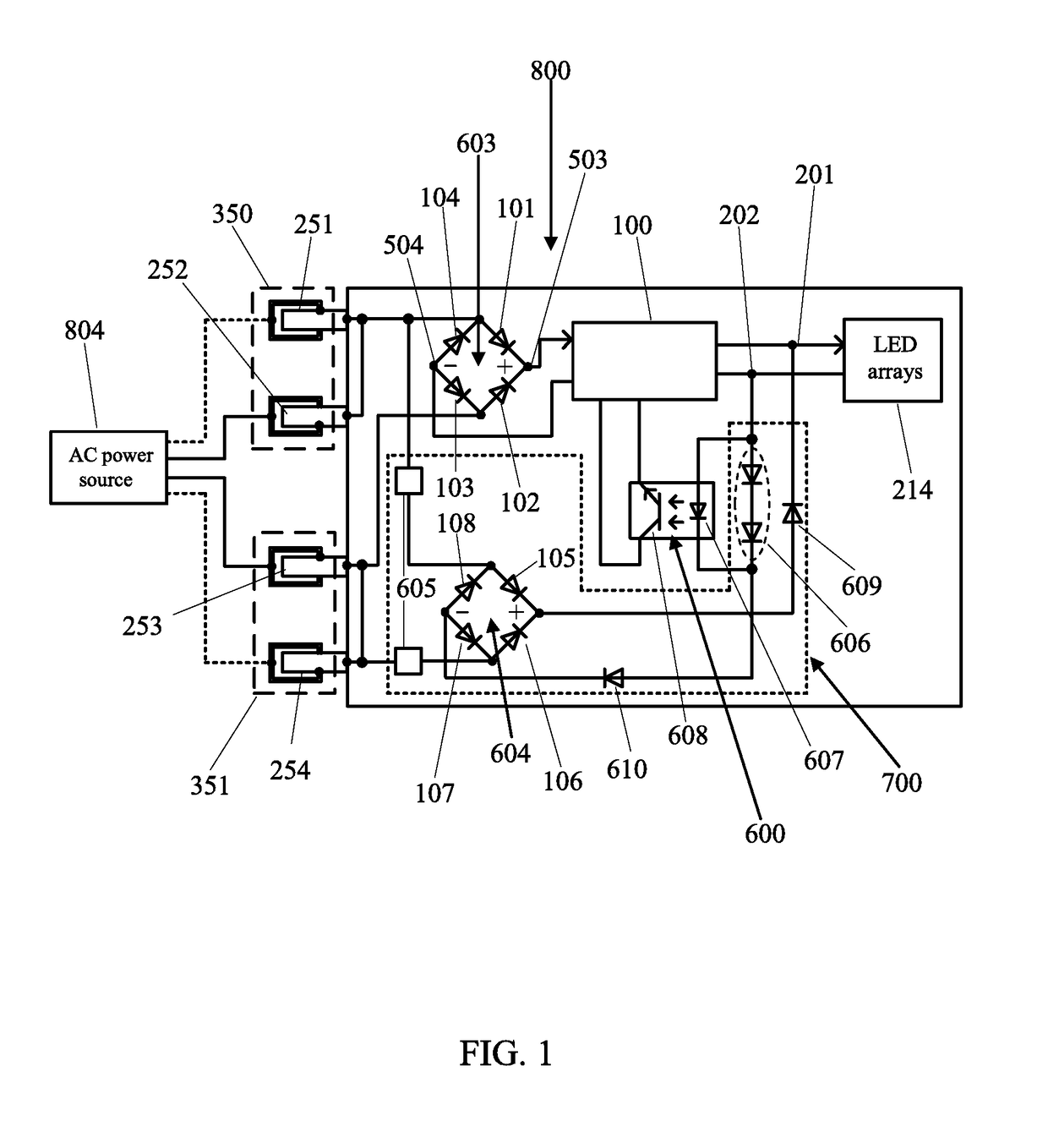
[0018]FIG. 1 is a block diagram of an LED lamp 800 operable with AC power sources that include AC mains and ballasts according to the present disclosure. The LED lamp 800 comprises one or more LED arrays 214; a lamp base portion comprising electrical conductors 251, 252, 253, and 254; a first full-wave rectifier 603; an optocoupler 600; a ballast operation circuit 700; and an LED driving circuit 100. The ballast operation circuit 700 comprises and a second full-wave rectifier 604, two frequency sensitive devices 605, and two or more diodes 606 connected in series. The first full-wave rectifier 603 receives power from an AC power source 804 via the four electrical conductors 251, 252, 253, and 254 and converts an AC voltage into a first DC voltage. The AC power source 804 may be a ballast or the AC mains. The electrical conductors 251 and 252 connect to a fixture socket 350, and the electrical conductors 253 and 254 connect to the other fixture socket 351. The LED driving circuit 100...


PUM


Abstract

An LED lamp, comprising a first full-wave rectifier, a ballast operation circuit, an LED driving circuit, LED array(s), and an optocoupler, replaces a fluorescent tube or a conventional LED tube lamp in lamp fixture sockets that are wired to connect to either AC mains or a ballast. The ballast operation circuit, comprising two frequency sensitive devices, a second full-wave rectifier, and two or more diodes connected in series, auto-selects an input AC voltage to operate the LED lamp without ambiguity and safety issues. When the input AC voltage is from the ballast, the optocoupler is enabled to disable the LED driving circuit, whereas the LED array(s) are powered by the second full-wave rectifier. When the input AC voltage is from the AC mains, the optocoupler is disabled to maneuver the LED driving circuit, whereas the LED array(s) are operated by the LED driving circuit, pre-powered by the first full-wave rectifier.

Description

CROSS-REFERENCE TO RELATED APPLICATIONS[0001]The present disclosure is part of a continuation-in-part (CIP) application of U.S. patent application Ser. No. 15 / 897,106, filed 14 Feb. 2018 which is a CIP application of U.S. patent application Ser. No. 15 / 874,752, filed 18 Jan. 2018, which is a CIP application of U.S. patent application Ser. No. 15 / 836,170, filed 8 Dec. 2017, which is a CIP application of U.S. patent application of Ser. No. 15 / 649,392 filed 13 Jul. 2017, which is a CIP application of U.S. patent application Ser. No. 15 / 444,536, filed 28 Feb. 2017 and issued as U.S. Pat. No. 9,826,595 on 21 Nov. 2017, which is a CIP application of U.S. patent application Ser. No. 15 / 362,772, filed 28 Nov. 2016, which is a CIP application of U.S. patent application Ser. No. 15 / 225,748, filed 1 Aug. 2016 and issued as U.S. Pat. No. 9,743,484 on 22 Aug. 2017, which is a CIP application of U.S. patent application Ser. No. 14 / 818,041, filed 4 Aug. 2015 and issued as U.S. Pat. No. 9,420,663 o...

Claims


Application Information

Patent Timeline
Patent Type & Authority Patents(United States)
IPC IPC(8): H05B33/08F21V23/06F21K9/278H05B44/00F21Y103/10F21Y115/10
CPCH05B33/0815F21K9/278F21V23/06H05B33/0845H05B33/089F21Y2115/10F21Y2103/10Y02B20/30H05B45/355H05B45/3578H05B45/375
Inventor HSIA, CHUNGHO
Owner ALEDDRA INC
Why Eureka
Try Eureka