
Cleaning head and cleaning device for cleaning a spinning rotor along with a method for cleaning a spinning rotor

Inactive Publication Date: 2018-12-04
RIETER INGOLSTADT GMBH
View PDF19 Cites 0 Cited by
  • Summary
  • Abstract
  • Description
  • Claims
  • Application Information

AI Technical Summary

Benefits of technology

The patent describes a cleaning device that has a scraper element for removing contaminants from the open edge of a spinning rotor. The scraper element is placed on the cleaning head and is fed into the spinning rotor to effectively remove these contaminants. This process is particularly useful for polyester materials that produce strong deposits. The cleaning head also has a positioning device to ensure proper placement and protection during movement. The technical effect of this invention is a reliable and efficient cleaning process that improves production efficiency and quality.

Problems solved by technology

During the operation of open-end spinning devices, upon their spinning, due to the constant contact of the fibers fed to the spinning rotor with the walls of the spinning rotor, and due to the fiber dust that arises, contaminants and deposits on the spinning rotor arise.
This may impair the quality of the yarn that is spun, and therefore must be removed at regular intervals.
However, with such cleaning devices provided with a brush, there is a risk that the detached contaminants will clog the bristles of the cleaning brush within a short time.
While the rotor groove of a spinning rotor is subjected, to a certain extent, to the depositing of dirt, contaminants may also arise in the area of the slide wall.
However, it has been found that such contaminants arise not only in the area of the rotor groove and the fiber slide wall.
Moreover, in the area directly at the open edge of the spinning rotor, over the course of time, such deposits (but those that are not picked up by conventional cleaning devices) arise.
Such contaminants are suddenly and unexpectedly detached during the spinning process, or crumble and then fall into the fiber collection groove.
This leads not only to quality impairments of the yarn that is drawn, but also quite frequently to yarn breaks.
In particular, this problem arises in the processing of polyester fibers, since, due to the various chemical additives for spinning preparation, these particularly tend to produce deposits on the fiber slide wall of the spinning rotor.

Method used


Image

  • Cleaning head and cleaning device for cleaning a spinning rotor along with a method for cleaning a spinning rotor
  • Cleaning head and cleaning device for cleaning a spinning rotor along with a method for cleaning a spinning rotor
  • Cleaning head and cleaning device for cleaning a spinning rotor along with a method for cleaning a spinning rotor

Examples


Embodiment Construction

[0044]Reference will now be made to embodiments of the invention, one or more examples of which are shown in the drawings. Each embodiment is provided by way of explanation of the invention, and not as a limitation of the invention. For example features illustrated or described as part of one embodiment can be combined with another embodiment to yield still another embodiment. It is intended that the present invention include these and other modifications and variations to the embodiments described herein.

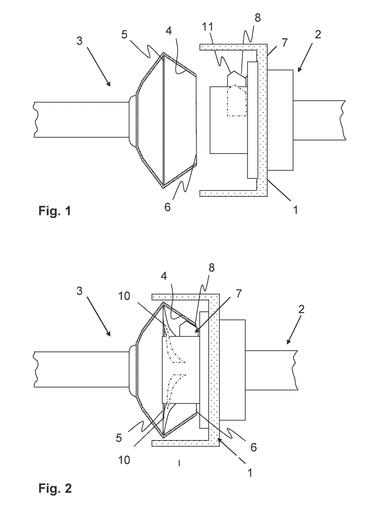
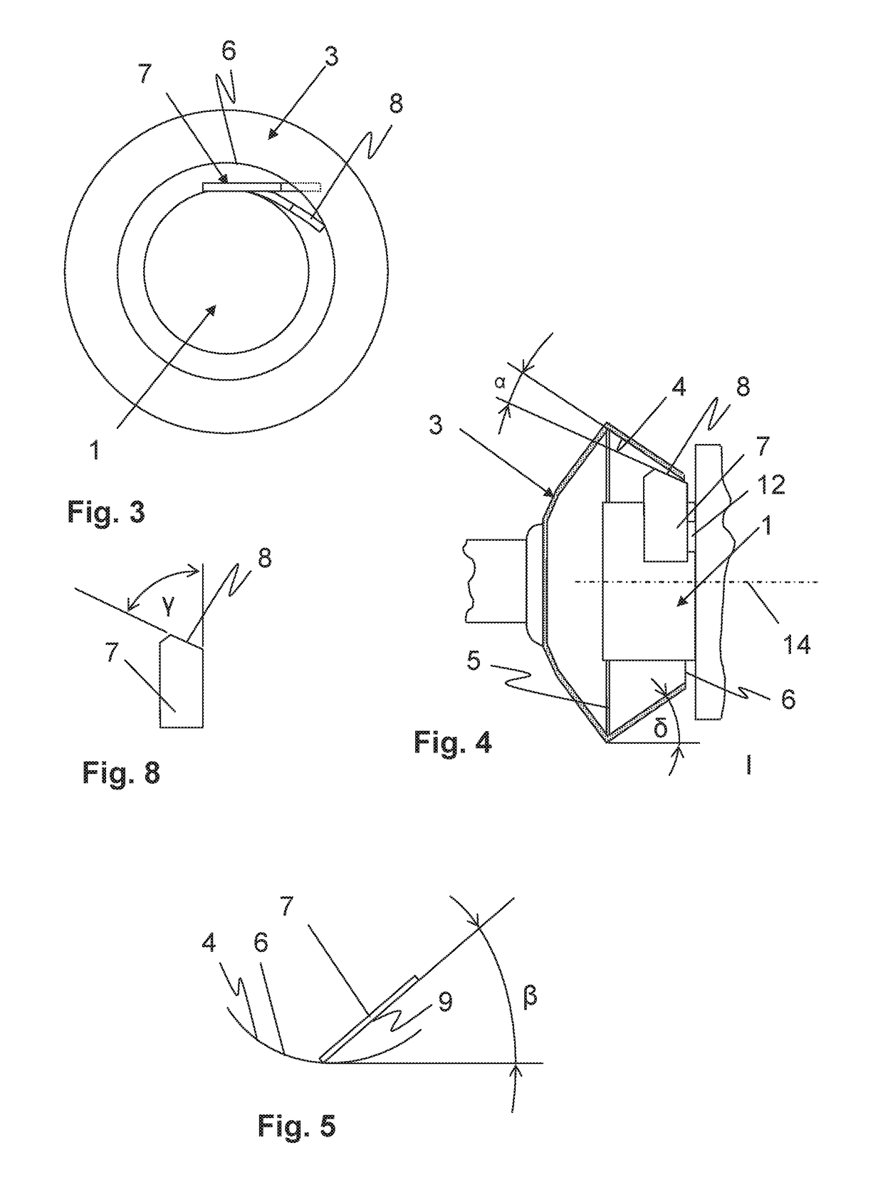
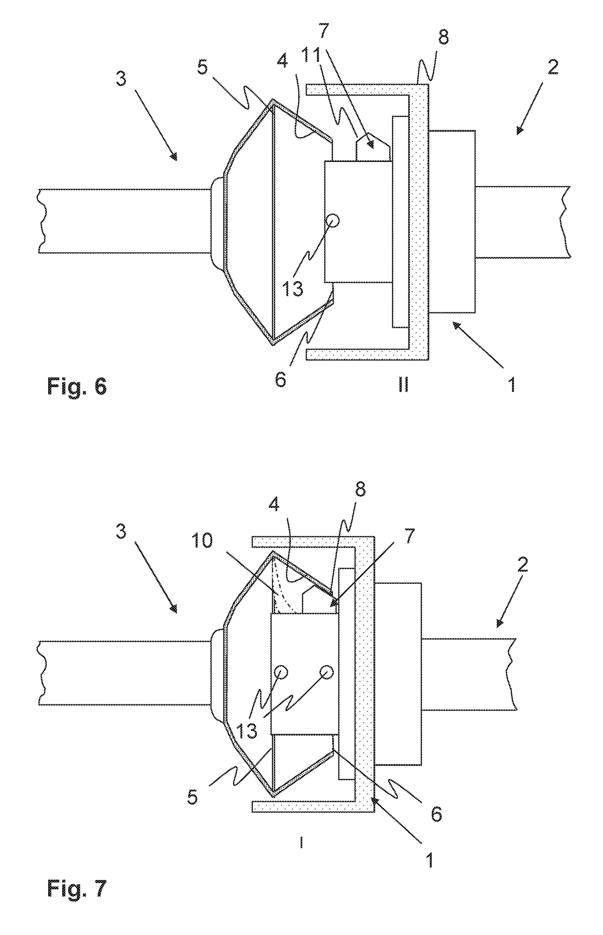
[0045]FIG. 1 shows a spinning rotor 3 and a cleaning head 1 of a cleaning device 2 in a schematic, partially sectional overview display. In a conventional manner, the spinning rotor 3 features a fiber slide wall 4, a fiber collection groove 5 and an open edge 6. While, with conventional cleaning devices 2, emphasis has always been placed on a particularly good cleaning of the fiber collection groove 5 and the fiber slide wall 4, the cleaning of the open edge 6 of the spinning rotor...


PUM

PropertyMeasurementUnit
Angleaaaaaaaaaa
Angleaaaaaaaaaa
Angleaaaaaaaaaa

Abstract

A cleaning head of a cleaning device for cleaning a spinning rotor, by means of a feed device, be fed into a predetermined cleaning position in the interior of the spinning rotor. The cleaning head has a cleaning element formed as a scraper element arranged in such a manner that, in the predetermined cleaning position of the cleaning head, it is fed to the open edge of the spinning rotor. A cleaning device for cleaning a spinning rotor features a corresponding cleaning head. With a method for cleaning a spinning rotor by means of the cleaning device, after feed of the cleaning head into the cleaning position, the open edge of the spinning rotor is cleaned by means of the scraper element.

Description

FIELD OF THE INVENTION[0001]The present invention relates to a cleaning head of a cleaning device for cleaning a spinning rotor featuring a fiber slide wall, a fiber collection groove and an open edge, wherein, by means of a feed device of the cleaning device, the cleaning head can be fed into a predetermined cleaning position in the interior of the spinning rotor. The cleaning head features at least one cleaning element formed as a scraper element. The invention also relates to a cleaning device with such a cleaning head and a method for cleaning a spinning rotor with the aid of a cleaning device.BACKGROUND[0002]During the operation of open-end spinning devices, upon their spinning, due to the constant contact of the fibers fed to the spinning rotor with the walls of the spinning rotor, and due to the fiber dust that arises, contaminants and deposits on the spinning rotor arise. This may impair the quality of the yarn that is spun, and therefore must be removed at regular intervals...

Claims


Application Information

Patent Timeline
IPC IPC(8): D01H4/24
CPCD01H4/24D01H4/22
Inventor BAIER, FRANKWIDNER, HARALDSTEPHAN, ADALBERTPOHN, ROMEO
Owner RIETER INGOLSTADT GMBH
Learn More