Combined shower

a shower and shower head technology, applied in the field of showers, can solve the problems of difficult use, difficult fixation, easy falling off, etc., and achieve the effects of improving stability, improving fixation, and convenient us

Active Publication Date: 2018-12-11
ZHEJIANG HUALE TECH CO LTD
View PDF7 Cites 3 Cited by
  • Summary
  • Abstract
  • Description
  • Claims
  • Application Information

AI Technical Summary

Benefits of technology

[0007]One objective of one embodiment of the present invention is to avoid the issues stated above in the prior art, and to provide a combined shower. The technical issue to be resolved is how to improve the convenience and stability of using the combined shower, while reducing the space occupation of the combined shower.

Problems solved by technology

And the longitudinal length is too long, having the issue of occupying a big space.
This requires a tall stature of the user, so it is quite difficult to use.
The fixation is not very stable and easy to fall off.

Method used


Image

  • Combined shower
  • Combined shower
  • Combined shower

Examples


first embodiment

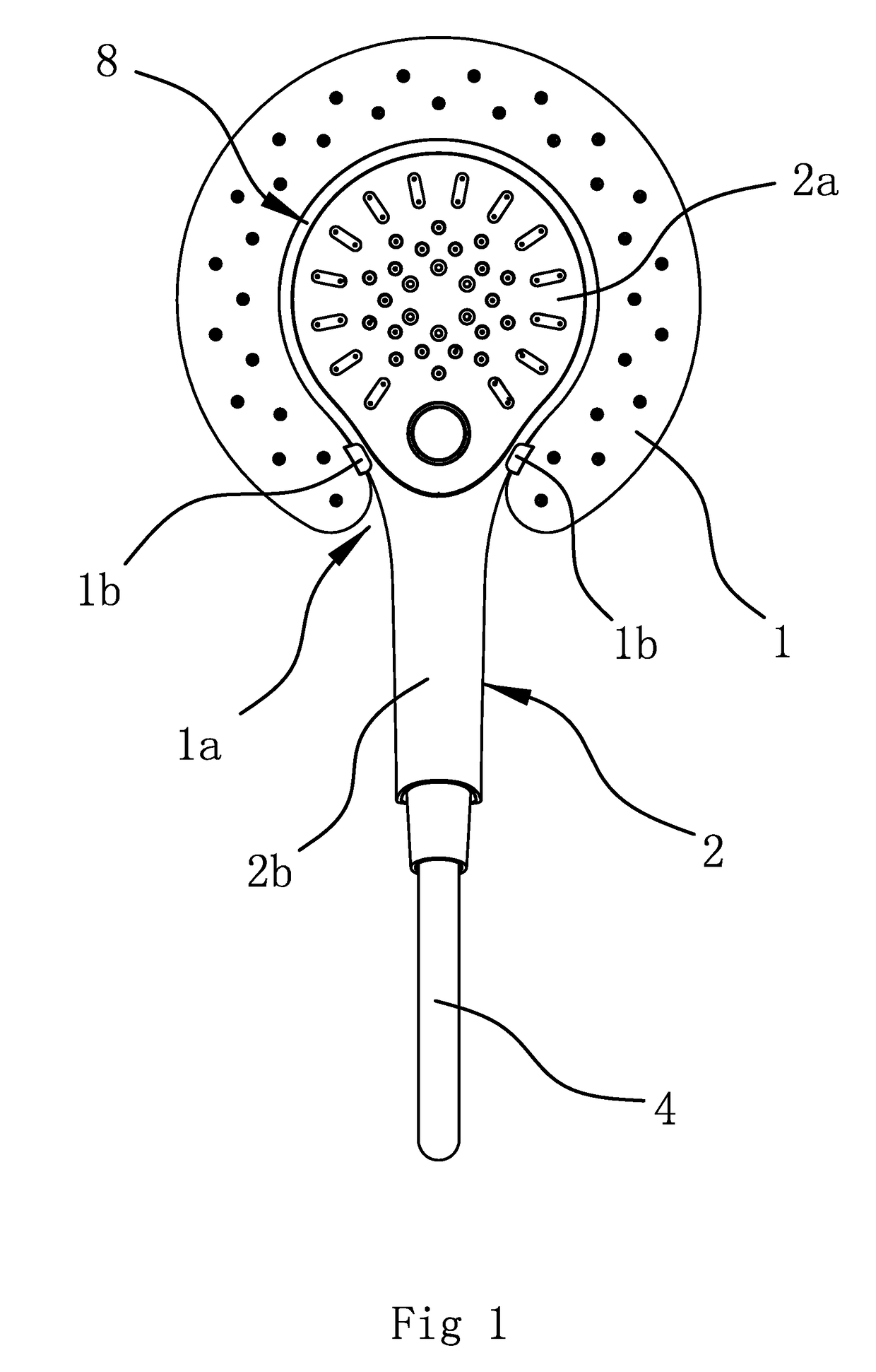
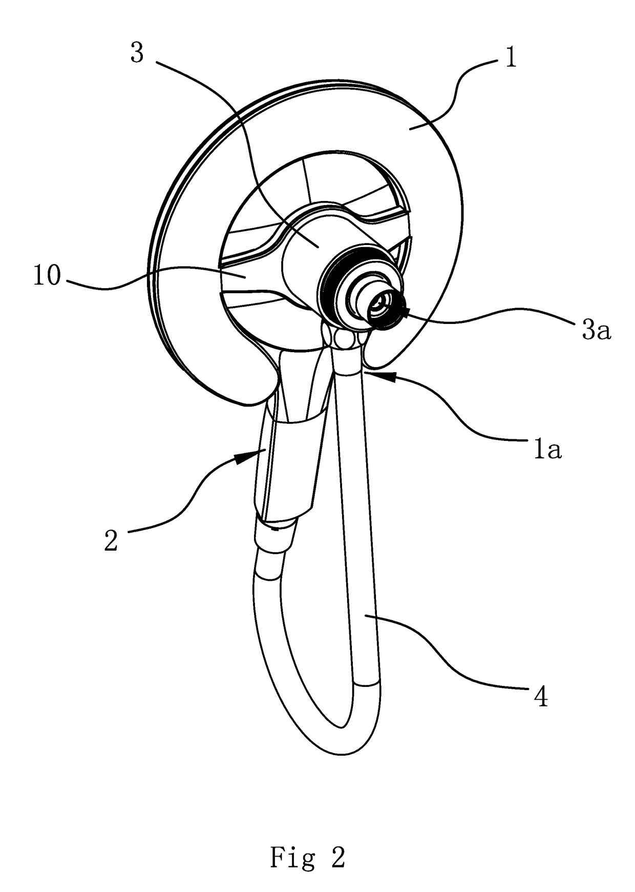
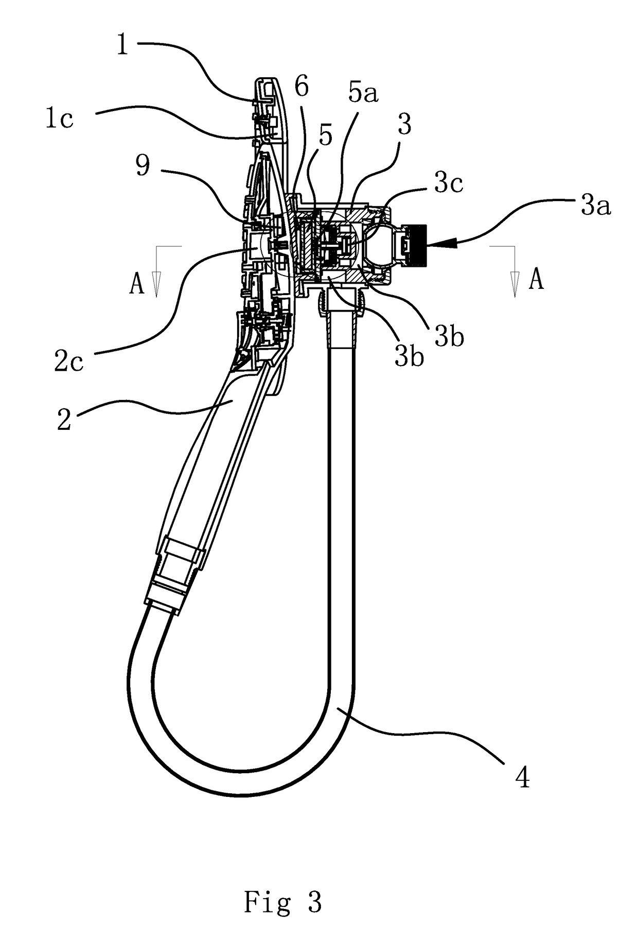
[0044]As shown in FIG. 1, FIG. 2 and FIG. 3, the present combined shower comprises a top shower head (1), a handheld shower head (2) and an assembly hub (3) which has a water inlet (3a). The top shower head (1) has the First Outlet Chamber (1c). The handheld shower head (2) has the Second Outlet Chamber (2c). The assembly hub (3) has a water inlet cavity (3b) inside that connects to the water inlet (3a). The Second Outlet Chamber (2c) of the handheld shower head (2) always connects to the water inlet cavity (3b) through the water hose (4).

[0045]Here, inside the assembly hub (3), there is also the first magnetic piece (5), an elastic piece (6) and a sealing structure which can connect or block the First Outlet Chamber (1c) of the top shower head (1) and the water inlet cavity (3b). Without any effects of external forces, under the action of the elastic force from the elastic piece (6), the first magnetic piece (5) moves and makes the sealing structure block the First Outlet Chamber (...

second embodiment

[0057]As shown in FIG. 6, this Second Embodiment is roughly the same as the technical proposal in First Embodiment. The differences are:

[0058]The sealing structure comprises a swinging plate (75) hinged on the front part of the water passage port (3d). The elastic piece (6) comprises a torsion spring connected to the hinge point. Under the action of the elastic force from the torsion spring, the swinging plate (75) can lean against the end of the water passage port (3d) and forms a seal. The first magnetic piece (5) is connected to the front side of the swinging plate (75) and can drive the swinging plate (75) to swing back and forth. Of course, the first magnetic piece (5) may also be connected to the rear side of the swinging plate (75) as needed.

[0059]When the top shower head (1) is not required to spray water, the second magnetic piece (9), along with the handheld shower head (2), is taken down. Under the action of the elastic force from the torsion spring, the swinging plate (7...

third embodiment

[0060]As shown in FIG. 7, this Third Embodiment is roughly the same as the technical proposal in First Embodiment. The differences are:

[0061]The sealing structure comprises a sheet-like sealing piece (76). The sealing piece (76) is fixed on the rear side of the first magnetic piece (5), and the sealing piece (76), along with the first magnetic piece (5) can tightly press against the end of the water passage port (3d) and forms a seal, under the action of the elastic force from the elastic piece (6).


PUM


Abstract

A combined shower comprising a top shower head and a handheld shower head, a first magnetic piece, an elastic piece and a sealing structure is inside an assembly hub of the top shower head. The first magnetic piece can move under the action of the elastic force from the elastic piece and then makes the sealing structure shut off the outflow cavity of the top shower head. The second magnetic piece is fixed on the handheld shower head and the second magnetic piece is arranged magnetically opposite and facing the first magnetic piece. Under the action of the attraction force from the second magnetic piece, the first magnetic piece can overcome the elastic force from the elastic piece, moves in the opposite direction, and makes the sealing structure connect the outflow cavity of the top shower head to the water inlet cavity.

Description

RELATED APPLICATIONS[0001]This application claims benefit of Chinese Patent Application No. CN201610897985.1, filed Oct. 14, 2016.[0002]The applications and all patents, patent applications, articles, books, specifications, other publications, documents, and things referenced herein are hereby incorporated herein in their entirety for all purposes. To the extent of any inconsistency or conflict in the definition or use of a term between any of the incorporated publications, documents, or things and the text of the present document, the definition or use of the term in the present document shall prevail.BACKGROUND OF THE INVENTIONField of Invention[0003]The present invention relates to the technical field of shower apparatus, and particularly to a combined shower.Related Art[0004]A shower apparatus is used for having a shower, and is a common device in shower rooms. In the current marketplace, the common shower apparatus comprises a top shower head, a handheld shower head and a mount...

Claims


Application Information

Patent Timeline
Patent Type & Authority Patents(United States)
IPC IPC(8): B05B1/16B05B15/62B05B1/18E03C1/06E03C1/02F16K31/00E03C1/04
CPCB05B1/1609B05B1/16B05B1/185B05B15/62E03C1/0409E03C1/06E03C1/025F16K31/00E03C1/0408B05B1/18B05B1/3006B05B12/002
Inventor LIN, HONGXINHE, GUIYONG
Owner ZHEJIANG HUALE TECH CO LTD
Why Eureka
Try Eureka