Drill

a drill bit and drill bit technology, applied in the field of drill bit, can solve the problems of inability to increase the position accuracy of the hole and the inner surface accuracy of the hole as expected, and the accuracy of the hole position and the inner surface accuracy did not increase as expected, so as to improve the positional precision of the hole and the working accuracy, and secure the bending strength of the tool.

Active Publication Date: 2018-12-11
HONDA MOTOR CO LTD
View PDF16 Cites 2 Cited by
  • Summary
  • Abstract
  • Description
  • Claims
  • Application Information

AI Technical Summary

Benefits of technology

[0012]In the invention according to claim 1, the pad is arranged on the line perpendicular to the thinning face.
[0013]The cutting resistance force applied to the thinning face is applied in a direction perpendicular to the thinning face. Chatter vibration occurs when left unattended. In the present invention, the pad is arranged on the line perpendicular to the thinning face so as to receive the cutting resistance force applied to the thinning face by the pad. As a result, chatter vibration can be suppressed.
[0014]Therefore, according to the present invention, there is provided a drill capable of improving the positional precision of the hole and the working accuracy on the surface of the hole.
[0015]In the invention according to claim 2, since the width of the margin portion is set smaller than the width of the pad, it is possible to secure a bending strength of the tool while reducing the cutting resistance in a radial direction due to the frictional resistance of the margin portion.
[0016]In the invention according to claim 3, the clearance angle is set in the range of 6° to 8° in a side view.
[0017]Since the pad exerts its effect immediately after cutting, the position accuracy of the hole and the working accuracy on the surface of the hole can be further enhanced.

Problems solved by technology

Because the cast hole is a hole as cast, it is inferior in dimensional accuracy.
However, it was found that chatter vibration occurred despite the addition of the pad portion.
As a result, the position accuracy of the hole and the inner surface accuracy of the hole did not increase as expected.

Method used


Image

  • Drill
  • Drill
  • Drill

Examples


example

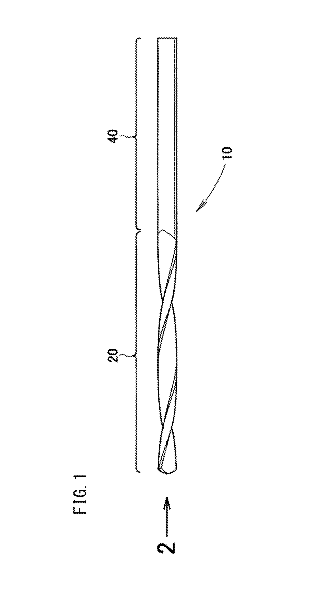
[0025]As shown in FIG. 1, a drill 10 includes a flute 20 and a shank 40 extending from the flute 20. The drill 10 is a sufficiently long cast hole drill.

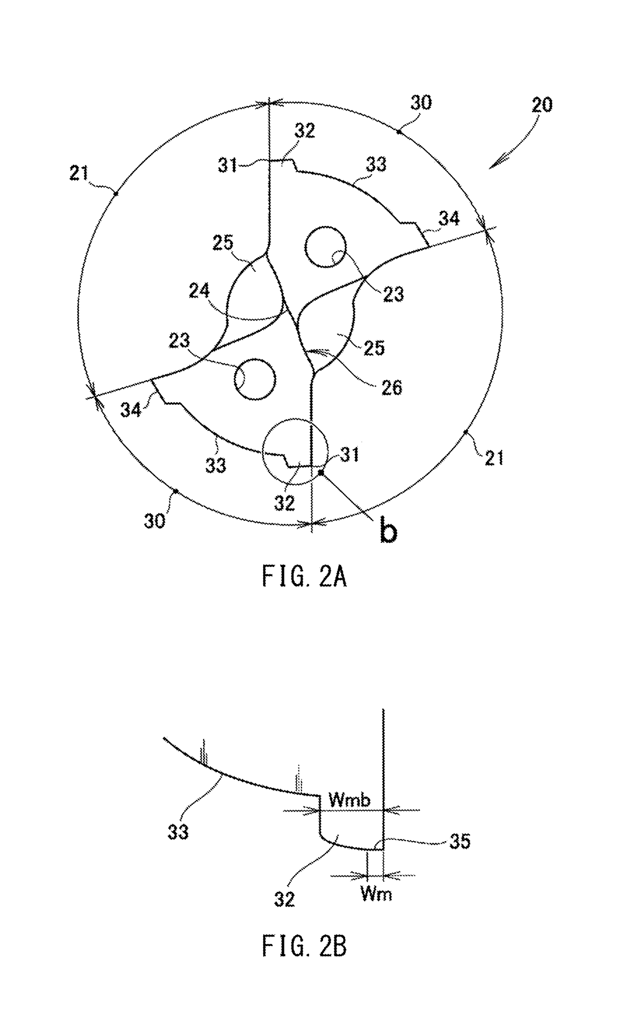
[0026]As shown in FIG. 2A, in a front view, the flute 20 alternately has two lands 30, 30 and two grooves 21, 21. Further, the flute 20 has two oil holes 23, 23 and a linear chisel edge 24.

[0027]As shown in FIG. 2B which is an enlarged view of the portion b of FIG. 2A, a margin 35 having a width Wm is included in a margin portion 32 having a width Wmb.

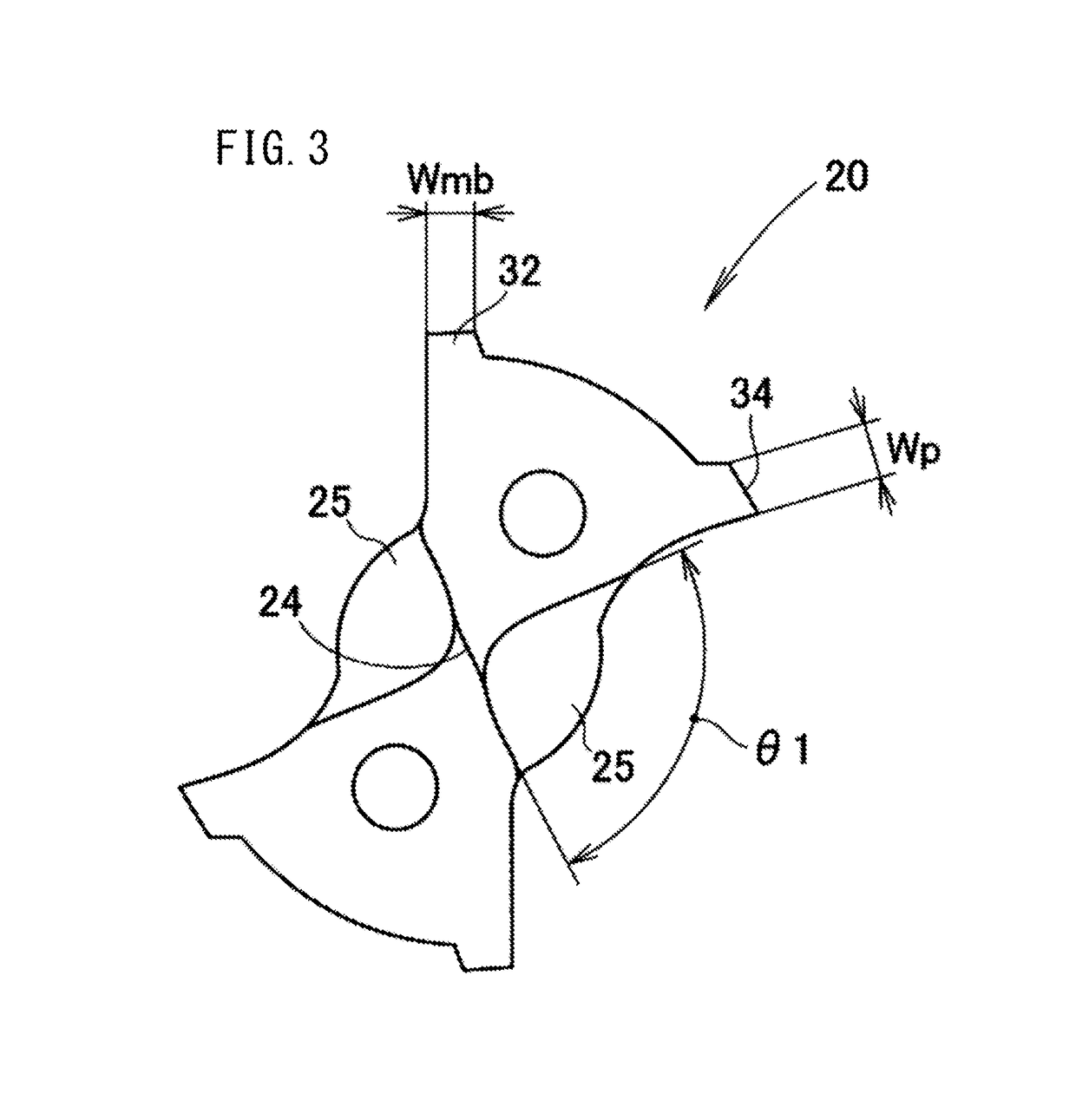
[0028]More specifically, the land 30 is provided with a margin portion 32 continuous from the cutting edge 31, a clearance 33 continuous from the margin portion 32 and having a diameter smaller than that of the margin portion 32, and a pad 34 continuous from the clearance 33 and having a width (Wp in FIG. 3) the same as a width Wmb of the margin portion 32. Preferably, the rear end of the pad 34 is connected to the groove 21.

[0029]As shown in FIG. 3, the chisel edge 24 is formed with a...


PUM


Abstract

A blade section has two lands and two flutes in an alternating manner and also has a linear chisel edge. The lands are each provided with: a margin section that is continuous with a cutting blade; a clearance section that is continuous with the margin section and that has a smaller diameter than the margin section; and a pad that is continuous with the clearance section and that has the same width as the width of the margin section.

Description

TECHNICAL FIELD[0001]The present invention relates to a drill suitable for machining a cast hole.BACKGROUND ART[0002]The cast hole is a hole formed in the casting by the pin attached to the mold. Because the cast hole is a hole as cast, it is inferior in dimensional accuracy. Therefore, it is preferable to add machining to the cast hole with a drill. The drill for this purpose is called a drill for a cast hole and various forms have been proposed (see, for example, Patent Document 1).[0003]The drill disclosed in Patent Document 1 includes a land portion generally called a margin portion and a pad portion disposed rearward from the land portion in the rotational direction. Further, a pad portion is provided in the land portion. The pad portion can enhance the straightness of the drill.[0004]However, it was found that chatter vibration occurred despite the addition of the pad portion. As a result, the position accuracy of the hole and the inner surface accuracy of the hole did not inc...

Claims


Application Information

Patent Timeline
Patent Type & Authority Patents(United States)
IPC IPC(8): B23B51/02B23B51/00
CPCB23B51/02B23B51/00B23B2251/04B23B2251/443B23B2251/18B23B2251/408B23B2251/043
Inventor FUKUSHIMA, HIROYUKIOSAWA, AKIHIROONOSE, JUNYAFUKUDA, TOSHIHIKO
Owner HONDA MOTOR CO LTD
Why Eureka
Try Eureka