Method and device for supplying energy into a scrap metal pile in an electric arc furnace

a scrap metal pile and electric arc furnace technology, which is applied in the field of supplying energy into scrap metal piles in electric arc furnaces, can solve the problems of significant overheating of the upper furnace chamber, temperature-related damage, and interference, and achieve the effects of large void volume, greater uneven distribution of void volume, and increased heat up of these areas

Inactive Publication Date: 2018-12-11
PRIMETALS TECH AUSTRIA GMBH
View PDF19 Cites 0 Cited by
  • Summary
  • Abstract
  • Description
  • Claims
  • Application Information

AI Technical Summary

Benefits of technology

[0017]Jets of hot gas behave differently in a scrap metal pile, depending on how the void volume is distributed over the scrap metal pile. The void volume, which is located between the bulky scrap present in the scrap metal pile and small pieces of scrap, is distributed as a function of the local distribution of these differently sized scrap pieces. A scrap metal pile, which is melted in an electric arc furnace, initially has a volume of up to 90% of void volume and 10% scrap, wherein the void volume is essentially formed by small pieces of scrap. If jets of hot gas are blown into a scrap metal pile, they preferably flow out of the channels melted by the jets through areas which have a large void volume and heat up these areas particularly intensively. When energy is supplied using jets of hot gas, the effects of an uneven distribution of the void volume is greater, and this greater energy supply is concentrated locally on few jets of hot gas.
[0018]The inventive method surprisingly has significant advantages when fossil energy is supplied by hot gas and electrical energy is supplied when melting scrap in an electric arc furnace.
[0019]In accordance with the invention and compared with conventional methods, a scrap metal pile has a reduced risk of overheating of the upper furnace chamber to temperatures above 1700° C., and therefore can be heated in an operationally reliable manner using hot gas.
[0020]This is achieved because energy is supplied by means of hot gas, without at the same time electrical energy being supplied by means of electric arcs. Furthermore, the energy quantity introduced by an individual jet of hot gas is limited, by the energy introduced by hot gas being divided into at least six, quantitative, and thus also limited jets, in view of the energy quantity transported thereby in each instance. The individual jets can be aligned such that they are not able to cross one another in the scrap metal pile. Otherwise, the energy quantity would once again be concentrated more than desired in accordance with the invention.
[0021]On account of these measures, hot gas passes through larger areas of the scrap metal pile compared with the prior art. This prevents small pieces in the scrap metal pile from only being rapidly heated locally and partially melted. This would have caused the scrap metal pile to have been particularly quickly compacted as a result of softening in these locally rapidly heated areas. The jets of hot gas, and further hot gases produced when the scrap metal pile is heated, can if necessary no longer flow through the scrap metal pile, because the flow resistance there has become too large. This also prevents part of the jets of hot gas, and the further hot gases produced when the scrap metal part is heated, from flowing back through the channels melted by the jets of hot gas, for instance at speeds of 700 to 900 m / s, and / or prevents blown jets of hot gas from being taken in again.
[0022]The invention avoids problems that occur in conventional methods of increasing the flow resistance in the scrap metal pile and back-flows into the channels in the upper furnace chamber melted by the jets of hot gas. This prevents the upper furnace chamber from being overheated and as a result damaged.

Problems solved by technology

However, there may occur interferences unwanted, significant overheating of the upper furnace chamber, in the area between the cover wall of the electric arc furnace and the surface of the scrap metal pile facing the cover wall.
However, at overheating to higher temperatures, temperature-related damage may occur.

Method used


Image

  • Method and device for supplying energy into a scrap metal pile in an electric arc furnace
  • Method and device for supplying energy into a scrap metal pile in an electric arc furnace

Examples


Embodiment Construction

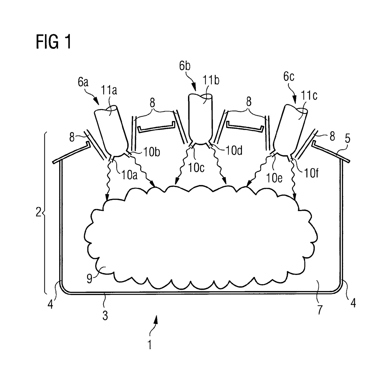
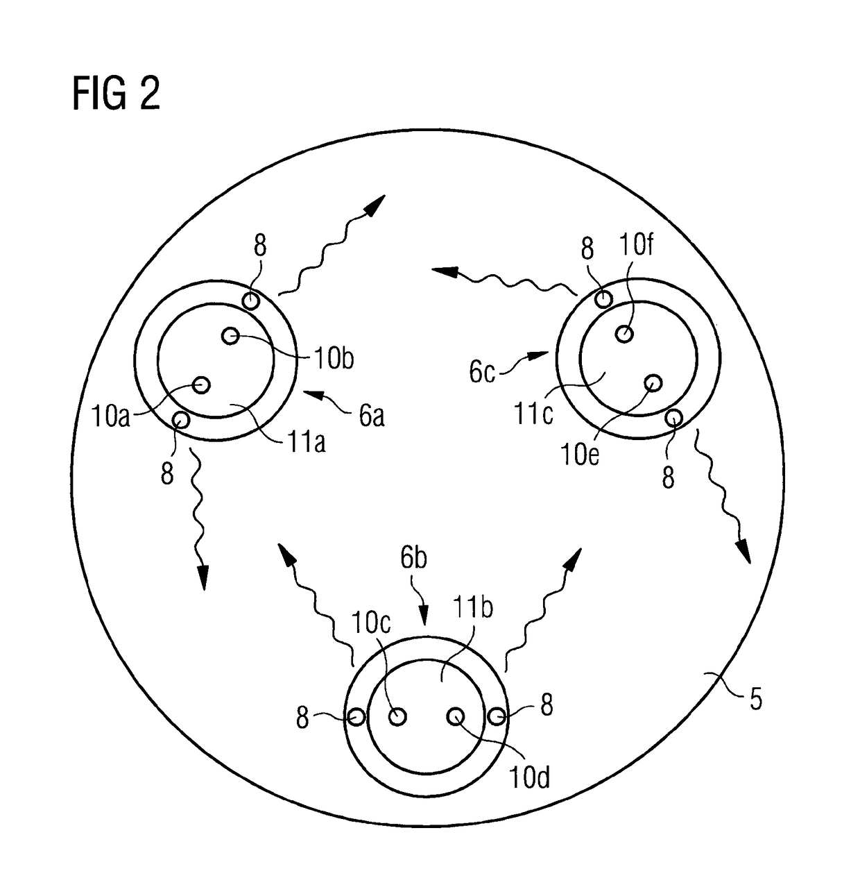
[0045]FIG. 1 shows a schematic and exemplary inventive apparatus 1 which is suited to implementing an inventive method, with an electric arc furnace 2 viewed from the side in cross-section. The electric arc furnace 2 has a base 3, side walls 4 and a cover wall 5. The inventive apparatus 1 also includes a number of blowing apparatus 6a, 6b, 6c for supplying reactant hot air into the interior 7 of the electric arc 2. Fuel supply apparatus 8 supply fuel to the jets of reactant hot air emerging from the blowing apparatuses 6a, 6b, 6c, in this case the fuel is natural gas. The exothermic reaction of the fuel, which is drawn into the jets of reactant hot air, produces jets of hot gas, shown schematically by wavy arrows. The jets of hot gas supply energy to the scrap metal pile 9 located in the interior 7 of the electric arc furnace 2. The blowing apparatus 6a, 6b, 6c preferably comprise overall six nozzles 10a, 10b, 10c, 10d, 10e, 10f all with nozzle openings. FIG. 1 shows the apparatus d...


PUM

PropertyMeasurementUnit
temperaturesaaaaaaaaaa
temperatureaaaaaaaaaa

Abstract

A method for supplying energy to a scrap metal pile (9) in an electric arc furnace (2). Energy is supplied by jets of hot gas in a first phase. Energy is supplied by electric arcs in a second phase after the first phase is completed. Hot gas is supplied via at least six jets. A device (1) for the method has an electric arc furnace (2), one or more blowing devices (6a, 6b, 6c), supply jets of reactant hot air into the chamber (7) of the electric arc furnace (8). The devices have a total of at least six nozzles (10a, 10b, 10c, 10d, 10e, 10f) with nozzle openings. Fuel conducting devices (8) supply fuel to the jets of reactant hot air.

Description

CROSS-REFERENCE TO RELATED APPLICATIONS[0001]The present application is a 35 U.S.C. §§ 371 national phase conversion of PCT / EP2013 / 072268, filed Oct. 24, 2013, which claims priority of German Patent Application No. 10 2012 020 788.3, filed Oct. 24, 2012, the contents of which are incorporated by reference herein. The PCT International Application was published in the German language.FIELD OF TECHNOLOGY[0002]The invention relates to a method for supplying energy into a scrap metal pile in an electric arc furnaceTECHNICAL BACKGROUNDPrior Art[0003]Methods are known, in which energy is supplied into a scrap metal pile in an electric arc furnace by means of the electric arc and also by jets of hot gas.[0004]German patent DE19521518 describes a method for introducing fossil energy into a scrap metal pile. At the same time as the supply of energy is by means of electric arcs and by jets of gases containing hot oxygen, channels are melted in a scrap metal pile and the further supply of foss...

Claims


Application Information

Patent Timeline
Patent Type & Authority Patents(United States)
IPC IPC(8): H05B11/00F27D13/00C21C5/52F27B3/08F27B3/20F27B3/22C21C5/56
CPCC21C5/565C21C5/5217F27B3/08F27B3/205F27B3/225F27D13/002F27B3/085Y02P10/216Y02P10/20
Inventor BROTZMANN, KARL
Owner PRIMETALS TECH AUSTRIA GMBH
Why Eureka
Try Eureka