Electronic device

a technology of electronic devices and electronic components, applied in the field of electronic devices, can solve the problems of increased manufacturing costs and increased cost of smaller electronic components, and achieve the effects of reducing the size of electronic devices, reducing manufacturing costs, and simple form

Active Publication Date: 2015-09-17
SEMICON ENERGY LAB CO LTD
View PDF4 Cites 52 Cited by
  • Summary
  • Abstract
  • Description
  • Claims
  • Application Information

AI Technical Summary

Benefits of technology

[0031]Part of a device like a watch is brought in contact with part of the body (wrist or arm) of a user, that is, the user wears the device, whereby the user can feel like the device is lighter than the actual weight. The use of a flexible secondary battery in an electronic device having a form with a curved surface that fits part of the body of a user allows the secondary battery to be fixed so as to have a form suitable for the electronic device.
[0032]When a user moves part of the body on which an electronic device is worn, the user might feel uncomfortable, regard the electronic device as a distraction, and feel stress even in the case where the electronic device has a curved surface that fits part of the body. In the case where at least part of an electronic device can be changed in form acc

Problems solved by technology

In this case, the manufacturing cost is increased bec

Method used


Image

  • Electronic device
  • Electronic device
  • Electronic device

Examples


embodiment 1

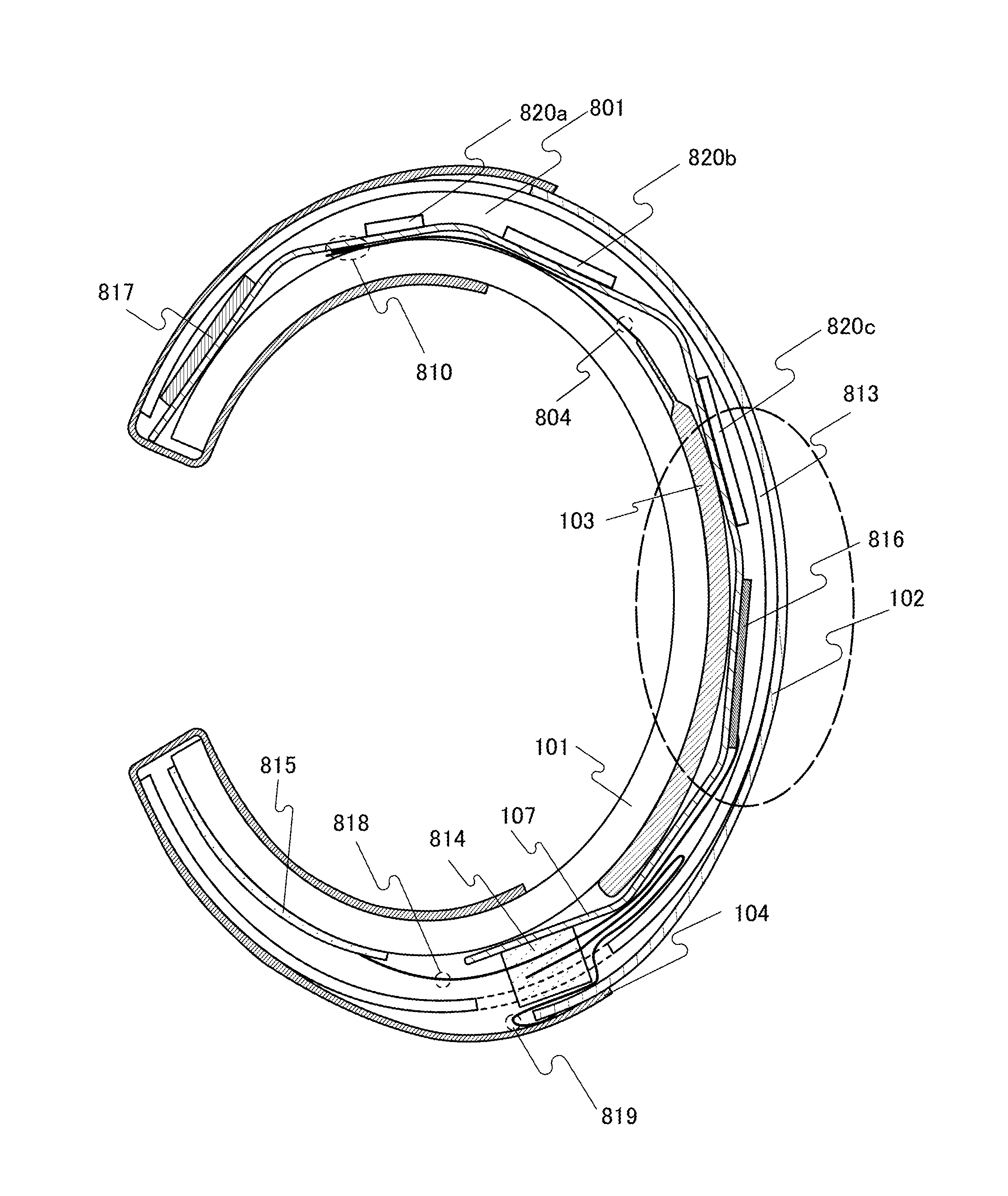
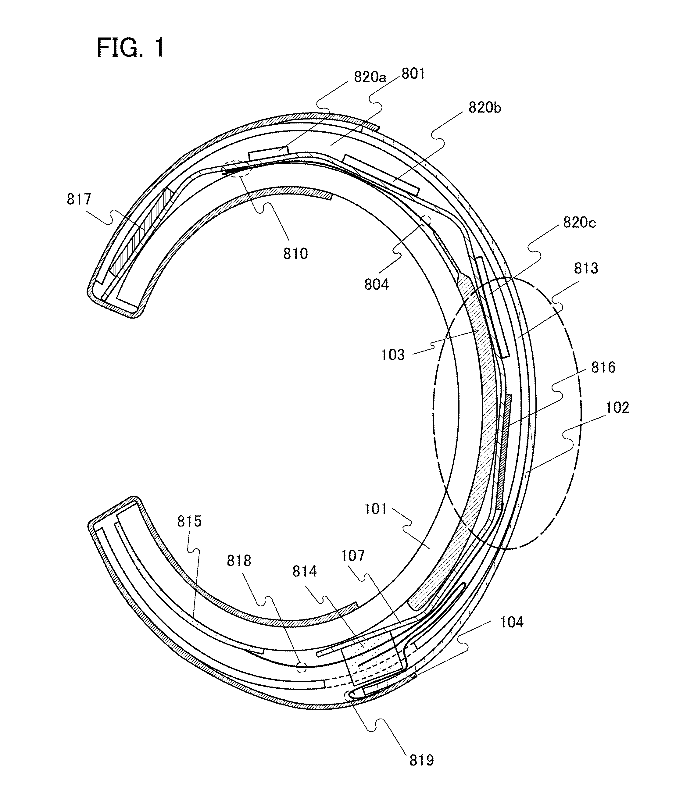
[0051]In this embodiment, an example of an electronic device that can be worn on a forearm of a user will be described.

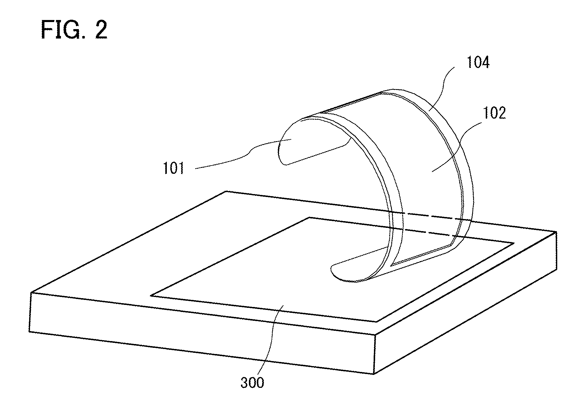
[0052]FIG. 1 is a cross-sectional schematic view of the electronic device, and FIG. 2 is a perspective view of a charger 300 and the electronic device.

[0053]The electronic device illustrated in FIG. 1 and FIG. 2 is a display device that can be worn on an arm and display an image or data. Since a flexible lithium-ion secondary battery is used, a shape that fits an arm can be achieved, and an appearance with an attractive design and the use as an accessory are enabled.

[0054]The electronic device illustrated in FIG. 1 and FIG. 2 includes a holding structure body 101, a secondary battery 103, a control board 107, a display portion 102, a protective film 813, and a cover 104. Specifically, the secondary battery 103 is provided in contact with the holding structure body 101, the control board 107 is provided over the secondary battery 103, the protective film 813 is provi...

embodiment 2

[0074]In this embodiment, an example of an electronic device whose internal structure is partly different from that of the electronic device described in Embodiment 1 will be described with reference to FIGS. 4A to 4C and FIGS. 5A and 5B.

[0075]In the structure illustrated in FIG. 4A, the position of the secondary battery is different from that in Embodiment 1.

[0076]The control board 107 is provided over the holding structure body 101, and the secondary battery 103 is fixed to the control board 107 with the buffer layer 801 therebetween. In FIG. 4A, the protective film 813 and the secondary battery 103 may be fixed to each other with an adhesive layer or the like.

[0077]In the structure illustrated in FIG. 4B, unlike in Embodiment 1, a second buffer layer 802 is further provided over the display portion 102. As the second buffer layer 802, an optical film such as polarizing film, a film for preventing a scratch or the like on a surface of the display portion 102, or the like is used. ...

embodiment 3

[0084]In this embodiment, an example of fabricating a lithium-ion secondary battery with the use of a film whose surface is embossed and provided with a pattern will be described.

[0085]First, a sheet made of a flexible base is prepared. As the sheet, a stack, a metal film provided with an adhesive layer (also referred to as a heat-seal layer) or sandwiched between adhesive layers, is used. As the adhesive layer, a heat-seal resin film containing, e.g., polypropylene or polyethylene is used. In this embodiment, a metal sheet, specifically, aluminum foil whose top surface is provided with a nylon resin and whose bottom surface is provided with a stack including an acid-proof polypropylene film and a polypropylene film, is used as the sheet. This sheet is cut to obtain a film 410 illustrated in FIG. 6A.

[0086]Then, the film 410 is embossed to form unevenness on the surface as illustrated in FIG. 6B so that the pattern can be visually recognized. Although an example in which the sheet is...


PUM


Abstract

A structure suitable for a portable information terminal or a wearable device is provided. In addition, an electronic device having a novel structure that can have various forms is provided. It is preferable that a buffer layer which absorbs a difference in the amount of change in form be provided between adjacent film substrates which overlap with each other. As the buffer layer, a gelled resin material, a rubber resin material, a liquid material, an air layer, or the like can be used. Furthermore, an optical film such as a polarizing film or a color filter may be used as the buffer layer. A plurality of buffer layers may be provided in an electronic device.

Description

TECHNICAL FIELD[0001]The present invention relates to an object, a method, or a manufacturing method. The present invention relates to a process, a machine, manufacture, or a composition of matter. One embodiment of the present invention relates to a semiconductor device, a display device, a light-emitting device, a power storage device, a driving method thereof, or a manufacturing method thereof. In particular, one embodiment of the present invention relates to an electronic device.[0002]Note that electronic devices in this specification mean all devices including secondary batteries, and electro-optical devices including secondary batteries, information terminal devices including secondary batteries, vehicles including secondary batteries, and the like are all electronic devices.BACKGROUND ART[0003]In recent years, portable information terminals typified by smartphones have been actively developed. Users desire portable information terminals, which are a kind of electronic device,...

Claims


Application Information

Patent Timeline
IPC IPC(8): G06F1/16
CPCG06F1/163G06F1/1643G06F1/1635G06F1/1652Y02E60/10G06F3/041G06F2203/04102
Inventor HIROKI, MASAAKIFURUMATSU, DAISUKE
Owner SEMICON ENERGY LAB CO LTD
Why Eureka
Try Eureka