Vehicle brake device

a brake device and vehicle technology, applied in the direction of braking systems, vehicles, instruments, etc., can solve the problems of unsuitable regeneration braking force, affecting the operation preventing the start of regeneration cooperative braking, so as to improve regeneration efficiency and reduce possible occurrence. , the effect of improving regeneration efficiency

Active Publication Date: 2014-04-03
ADVICS CO LTD
View PDF9 Cites 8 Cited by
  • Summary
  • Abstract
  • Description
  • Claims
  • Application Information

AI Technical Summary

Benefits of technology

[0009]According to the conventional technology explained above, since once the regeneration cooperative braking operation is prohibited after the ABS control ended, the regeneration efficiency becomes worse. Even if the regeneration cooperative braking operation is re-started after the ABS control ended, the ABS control is not necessarily re-started by the sure establishment of the ABS control starting condition. In other words, such condition depends on the change of the brake operating state or the amount of the regeneration braking force and in some cases such condition may not be established, allowing a chance of regeneration braking force to be generated. It is expected that the regeneration efficiency can be improved by reducing possible occurrence of repetitive hunting in which the starting and ending of the ABS control and ON / OFF of the regeneration braking operation within the one braking operation period.
[0010]The present invention was made in consideration with the above problems and the object of the invention is to provide a vehicle brake device which can improve a regeneration efficiency compared to a conventional device by generating a regeneration braking force within a range that a likelihood of re-starting of an ABS control after the ABS control ended for one braking operation period would not be increased.

Problems solved by technology

This is because the regeneration braking force is not suitable for a sensitive braking operation by the ABS control.
Under such braking force transferring, a discontinuous application of the braking force is generated, which gives an uncomfortable feeling to the operator of the vehicle.
Accordingly, such re-starting of regeneration cooperative braking operation is prohibited due to an increase of likelihood of generations of discontinuous application of braking force due to a repetitive ON / OFF operation of the regeneration braking force application.
According to the conventional technology explained above, since once the regeneration cooperative braking operation is prohibited after the ABS control ended, the regeneration efficiency becomes worse.
In other words, such condition depends on the change of the brake operating state or the amount of the regeneration braking force and in some cases such condition may not be established, allowing a chance of regeneration braking force to be generated.

Method used


Image

  • Vehicle brake device
  • Vehicle brake device
  • Vehicle brake device

Examples


first embodiment

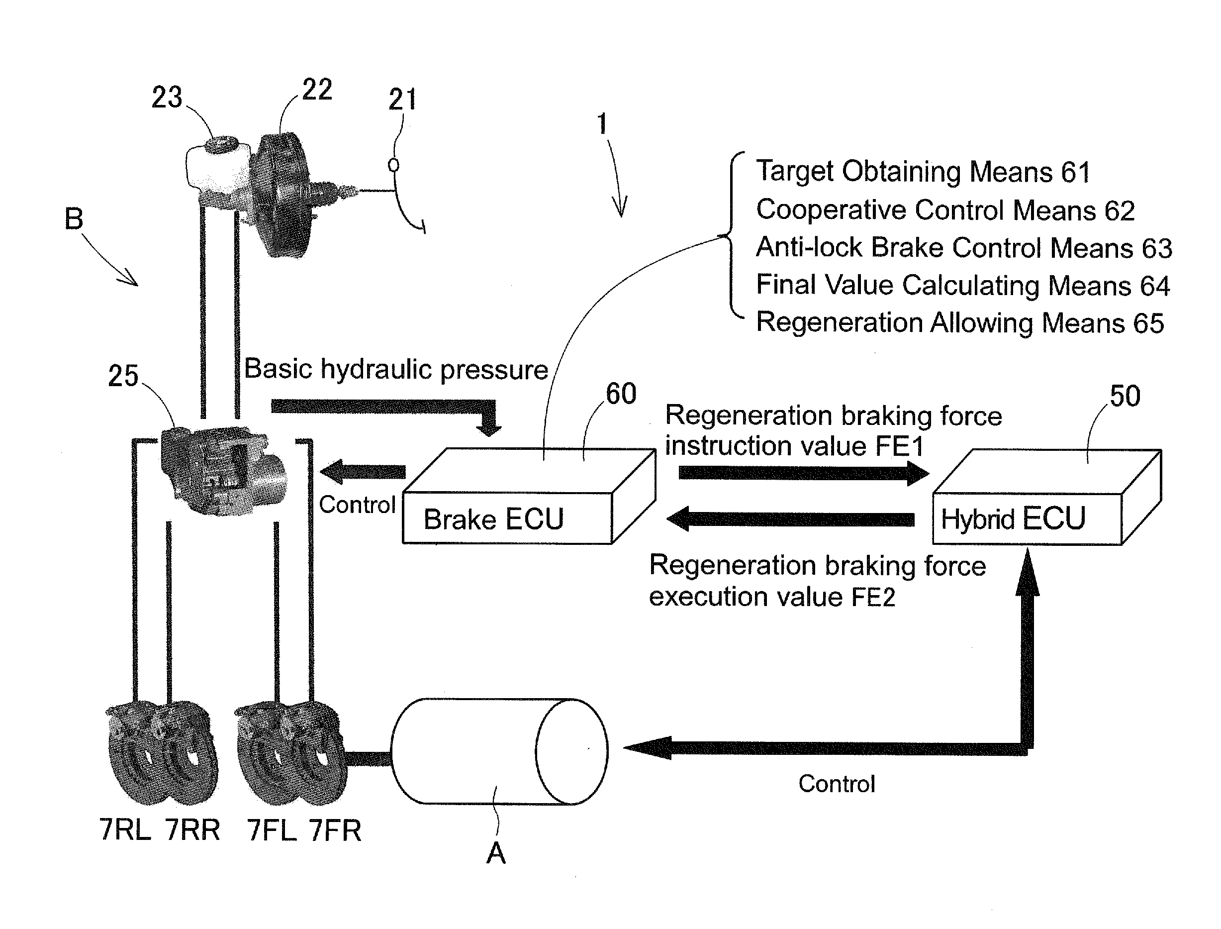
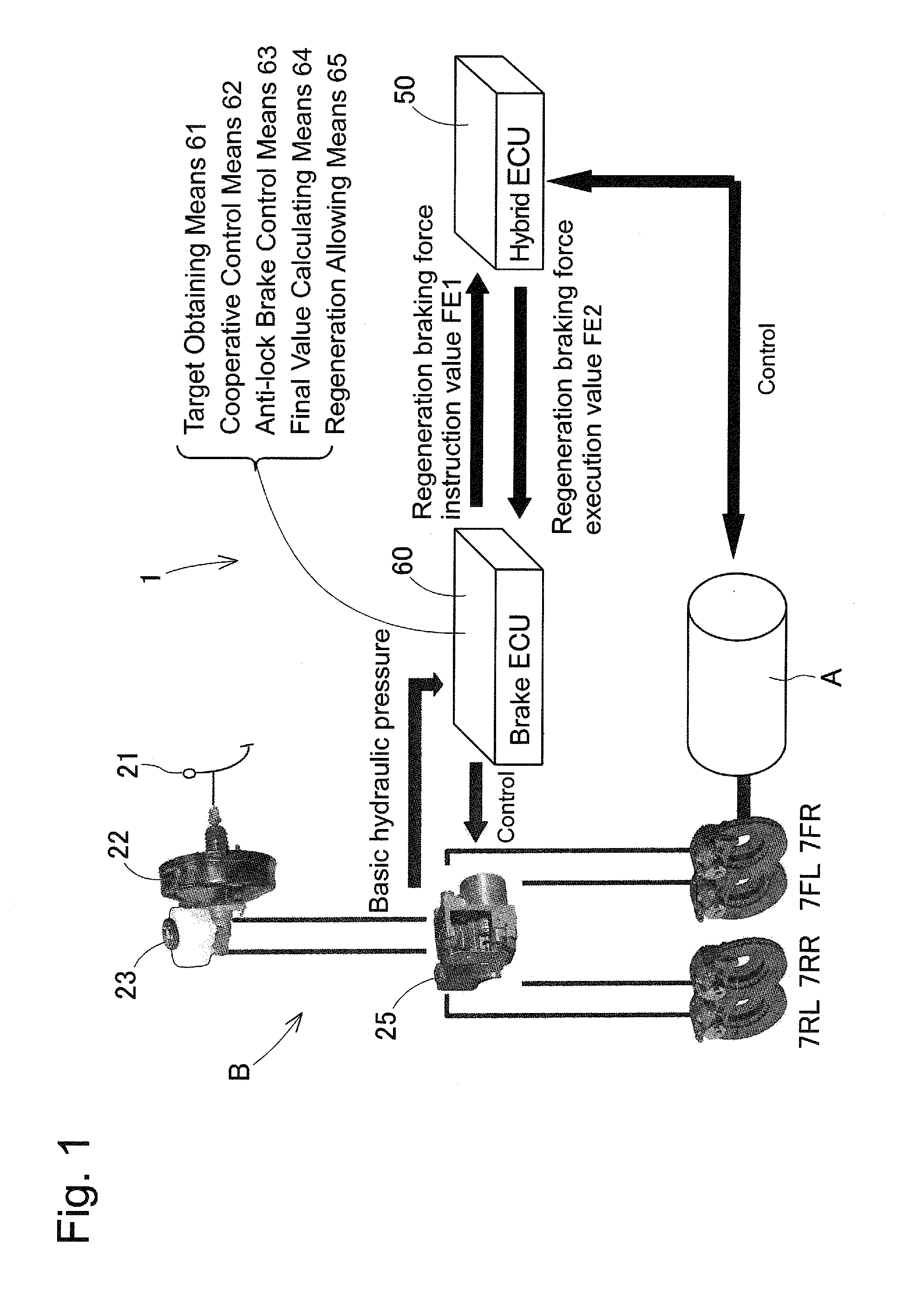
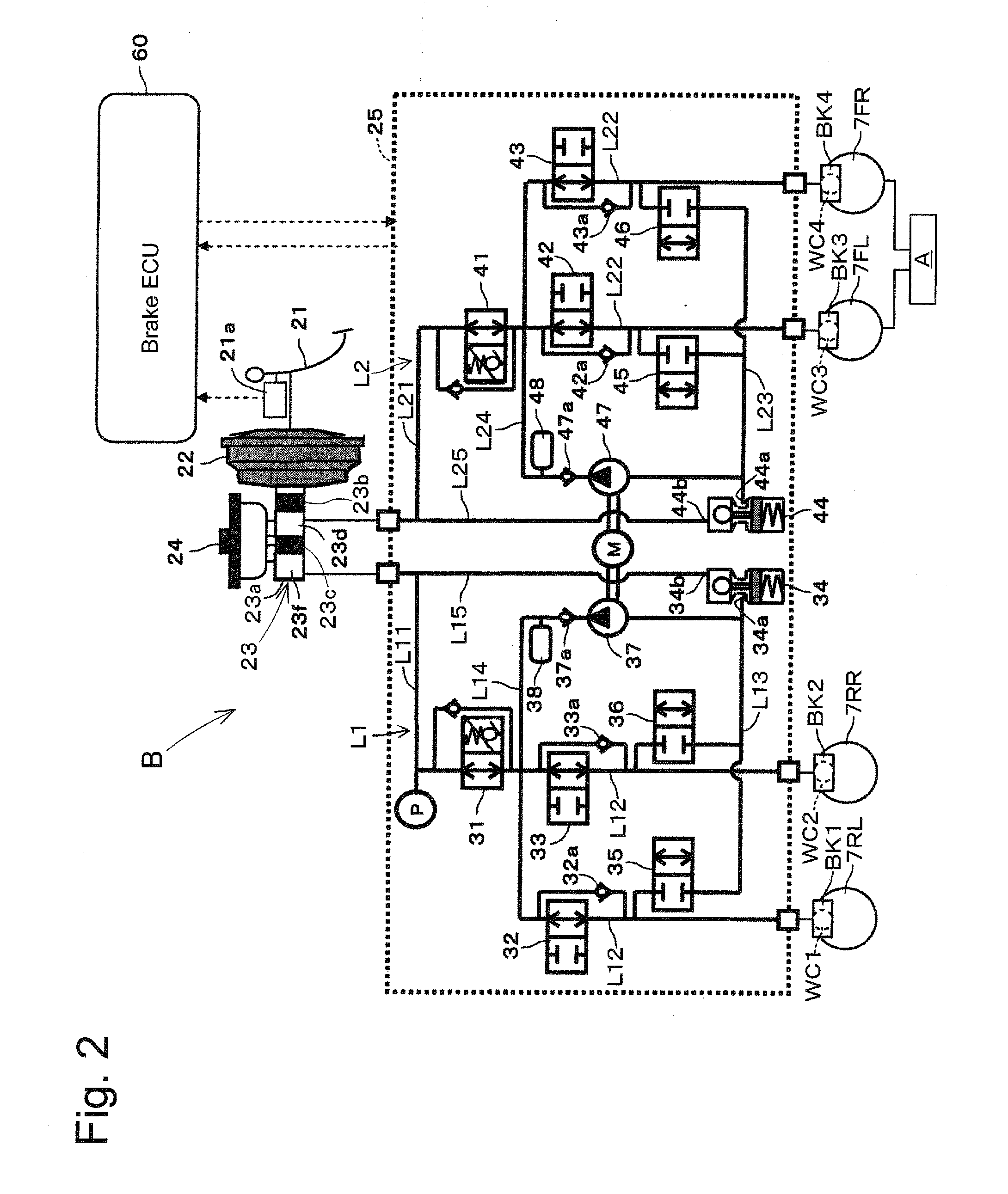
[0038]The hydraulic pressure control unit 25 is formed by the hydraulic control valves 31 and 41, the pressure increase control valves 32, 33, 42 and 43 and the pressure decrease control valves 35, 36, 45 and 46, pressure modulating reservoirs 34 and 44, pumps 37 and 47 and motor M. the components of the unit 25 is packaged and housed in one case. As shown in FIG. 2, the brake conduit system of the hydraulic brake device B according to the invention is formed by a front / rear conduit system having a first conduit system L1 which applies hydraulic pressure braking force to the rear right wheel 7RR and the rear left wheel 7RL and a second conduit system L2 which applies hydraulic pressure braking force to the front right wheel 7FR and the front left wheel 7FL. The first hydraulic pressure chamber 23d of the master cylinder 23 is connected to the second conduit system L2 and the second hydraulic pressure chamber 23f is connected to the first conduit system L1.

[0039]First, the first cond...

third embodiment

[0087]According to the vehicle brake device of the third embodiment, the operation under a transitional condition where the ABS control means 63 ended the operation and operation is transferred to the cooperative control means 62 does not become complicated and the operation is stabilized to suppress the influence by various types of disturbance.

[0088]It is noted that according to the embodiments explained above, allowable maximum regeneration braking force FEmax2 after the ABS control ended can be obtained by the function f(FK) corresponding to the magnitude of the ABS estimated available force FK. The function f(FK) can be freely set. Qualitatively, if a large regeneration braking force FE is allowed, the regeneration efficiency can be highly improved. However, under such situation the influence when the ABS control means 63 is re-started becomes large. Reversely, if a small regeneration braking force FE is allowed, the regeneration efficiency cannot be highly improved. However, t...


PUM


Abstract

A vehicle brake device comprises a hydraulic brake device, a regeneration brake device and a brake control device. The brake control device further includes a final value calculating device for calculating the target braking force FR at the time when an ABS control period ended and the cooperative control device restarted the operation to be as a regeneration allowing braking force FH, when the anti-lock brake control device has operated for the ABS control period within one braking operation period where the brake operating member is continuously operated and a regeneration allowing device operable after the ABS control period ended within the one braking operation period and after the cooperative control device restarted the operation and allowing the generation of the regeneration braking force FE only when the target braking force is less than a value of the regeneration allowing braking force FH.

Description

CROSS REFERENCE TO RELATED APPLICATIONS[0001]This is a National Stage of International Application No. PCT / JP2012 / 068607 filed Jul. 23, 2012, claiming priority based on Japanese Patent Application No. 2011-161982 filed Jul. 25, 2011, the contents of all of which are incorporated herein by reference in their entirety.TECHNICAL FIELD[0002]This invention relates to a brake device for a vehicle equipped with a hydraulic brake device and a regeneration brake device, and more particularly, to a braking operation process after ending of an anti-lock braking control operation by a brake control device which cooperatively controls the hydraulic brake device and the regeneration brake device.BACKGROUND OF THE TECHNOLOGY[0003]A hybrid vehicle which has both engine and motor / generator as a running drive source is generally structured to accumulate electric energy regenerated from the kinetic energy by the motor / generator during braking operation thereby to improve the fuel efficiency. In this s...

Claims


Application Information

Patent Timeline
Patent Type & Authority Applications(United States)
IPC IPC(8): B60L7/26B60T13/58
CPCB60T13/586B60L7/26B60T1/10B60T13/146B60T13/662B60T13/686B60T2270/602B60T2270/604B60T8/4872
Inventor NISHIO, AKITAKANAITO, MASAYUKIMATSUURA, MASAHIRO
Owner ADVICS CO LTD
Why Eureka
Try Eureka