Method of controlling fuel cell system

Active Publication Date: 2013-03-14
HONDA MOTOR CO LTD
View PDF2 Cites 20 Cited by
  • Summary
  • Abstract
  • Description
  • Claims
  • Application Information

AI Technical Summary

Benefits of technology

[0011]In the present invention, it becomes possible to suppress degradation of the fuel cell, and effectively collect regenerative electric power.
[0012]That is, in the present invention, during regeneration or when regeneration is expected to occur, output voltage of the fuel cell is set to a voltage value outside the oxidation reduction progress voltage range where oxidation reduction proceeds. Therefore, it becomes possible to suppress degradation of the fuel cell.
[0013]Further, in the present invention, during regeneration, or when regeneration is expected to occur, the amount of the reactant gas supplied to the fuel cell is changed based on the amount of electric power remaining in the energy storage device (SOC of the

Problems solved by technology

In this case, excessive electric power generated by the fuel cell is supplied to the battery for charging.
As the frequency of charging and discharging the battery increases, loss in electric power due to charging/discharging becomes large, and the output efficiency in the fuel cell system becomes low as a whole.
However, when the lower limit reference value of the output range is decreased, the output voltage of the fuel cell 1 is increased, and oxid

Method used


Image

  • Method of controlling fuel cell system
  • Method of controlling fuel cell system
  • Method of controlling fuel cell system

Examples


Embodiment Construction

1. Description Regarding Overall Structure

[1-1. Overall Structure]

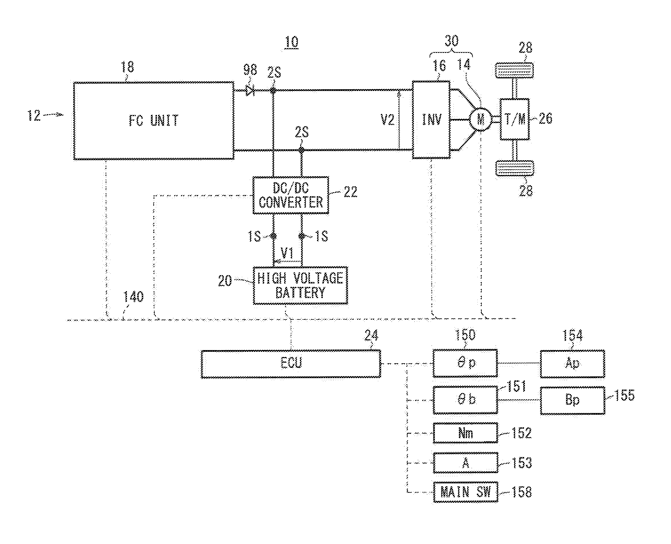
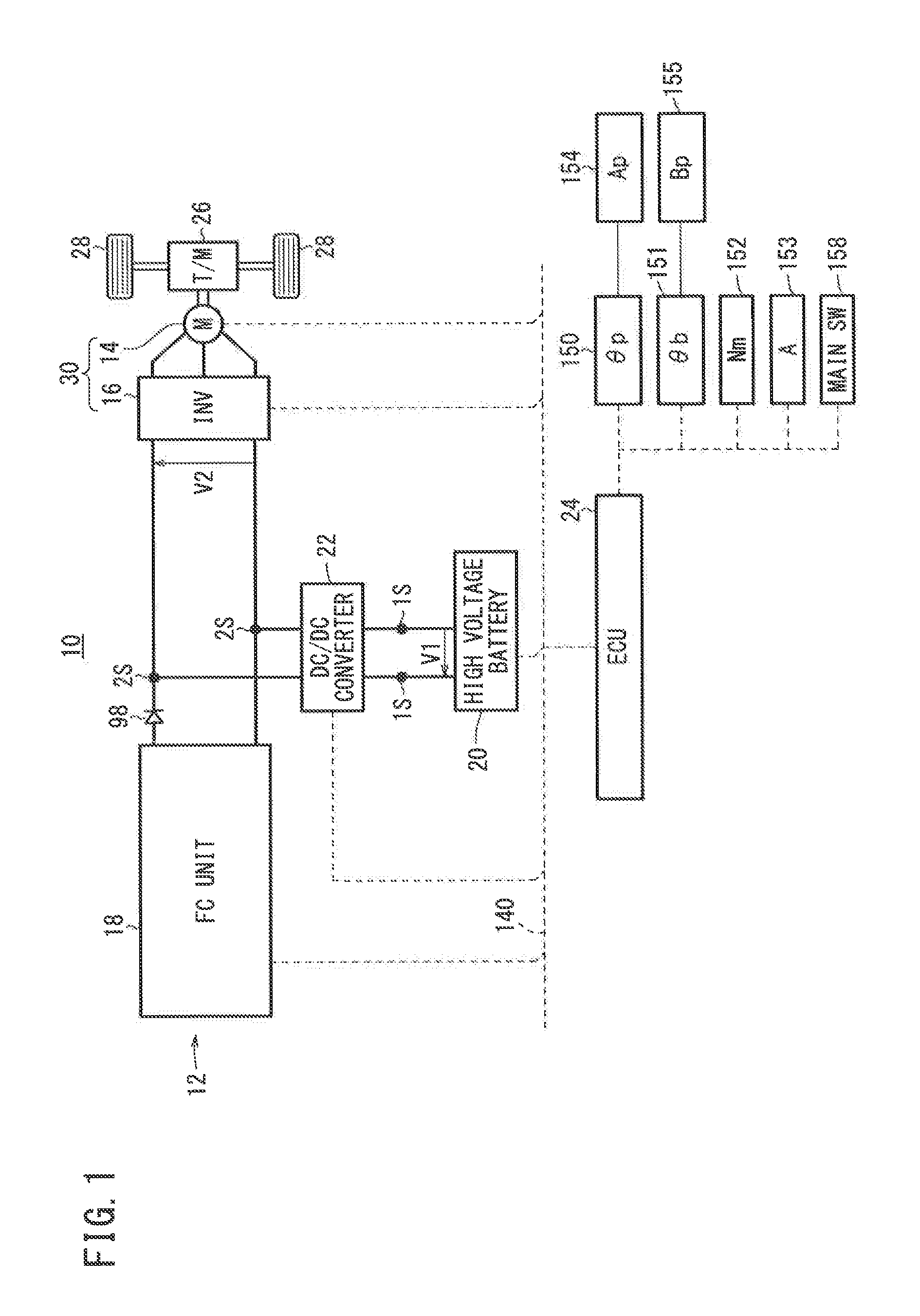
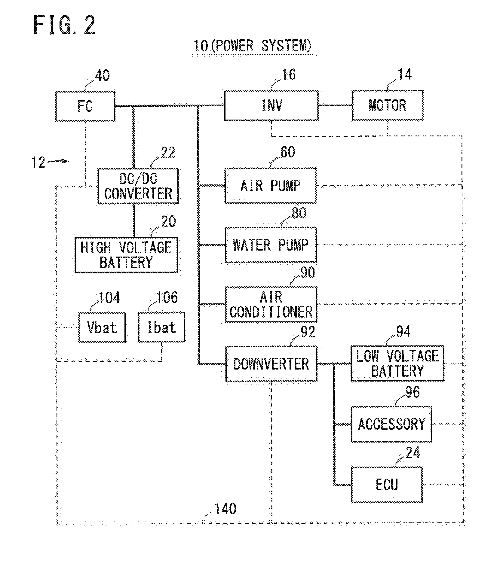
[0044]FIG. 1 is a diagram schematically showing the overall structure of a fuel cell vehicle (moving body) 10 (hereinafter referred to as the “FC vehicle 10” or “vehicle 10”) equipped with a fuel cell system 12 (hereinafter referred to as the “FC system 12”) according to an embodiment of the present invention. FIG. 2 is a block diagram showing a power system of the FC vehicle 10. As shown in FIGS. 1 and 2, the FC vehicle 10 includes a traction motor 14 and an inverter (auxiliary device) 16 in addition to the FC system 12.

[0045]The FC system 12 includes a fuel cell unit 18 (hereinafter referred to as the “FC unit 18”), a high voltage battery (hereinafter referred to as the “battery 20”) (energy storage device), a DC / DC converter 22, and an electronic control unit (control device) 24 (hereinafter referred to as the “ECU 24”).

[1-2. Drive System]

[0046]The motor 14 generates a driving force based on the electric power supp...


PUM


Abstract

In a fuel cell system, regeneration-time voltage fixed control is implemented where during regeneration or when regeneration is expected to occur, output voltage of a fuel cell is set to a voltage value outside an oxidation reduction progress voltage range, and the amount of reactant gas supplied to the fuel cell is changed based on the amount of electric power remaining in an energy storage device. In the regeneration-time voltage fixed control, it is determined whether or not regeneration occurs while a moving body equipped with the fuel cell system is moving down a slope, and in the case where it is determined that regeneration occurs while the moving body is moving down a slope, the amount of the reactant gas supplied to the fuel cell is decreased in comparison with the case where it is determined that regeneration occurs while the moving body is not moving down a slope.

Description

CROSS-REFERENCE TO RELATED APPLICATION[0001]This application is based upon and claims the benefit of priority from Japanese Patent Application No. 2011-196603 filed on Sep. 9, 2011, of which the contents are incorporated herein by reference.BACKGROUND OF THE INVENTION[0002]1. Field of the Invention[0003]The present invention relates to a method of controlling a fuel cell system which has a fuel cell and an energy storage device, and which is capable of regenerating electric power.[0004]2. Description of the Related Art[0005]In a conventional technique, a fuel cell system for suppressing degradation of a fuel cell used in a fuel cell vehicle or the like is proposed, and in the fuel cell system, power generation is performed in a manner that the oxidation reduction electrical potential is avoided (U.S. Patent Application Publication No. 2009 / 0029197 (hereinafter referred to as “US 2009 / 0029197 A1”)). In the fuel cell system disclosed in US 2009 / 0029197 A1, even if electric power requi...

Claims


Application Information

Patent Timeline
IPC IPC(8): H02J7/00H01M16/00
CPCY02E60/50H01M8/0488B60L2200/26H01M8/04753H01M16/006Y02E60/10
Inventor SHIRASAKA, TAKUYASAEKI, HIBIKIWATANABE, KAZUNORIKAZUNO, SHUICHI
Owner HONDA MOTOR CO LTD
Why Eureka
Try Eureka