Control apparatus for work machine

a control apparatus and work machine technology, applied in the direction of fluid couplings, couplings, transportation and packaging, etc., can solve the problems of difficult supply of pressurized oil, energy loss or fuel inefficiency, etc., and achieve accurate hoist rotary work, good speed matching, and no reduction in the lifting speed of the boom

Inactive Publication Date: 2012-01-03
KOMATSU LTD
View PDF10 Cites 9 Cited by
  • Summary
  • Abstract
  • Description
  • Claims
  • Application Information

AI Technical Summary

Benefits of technology

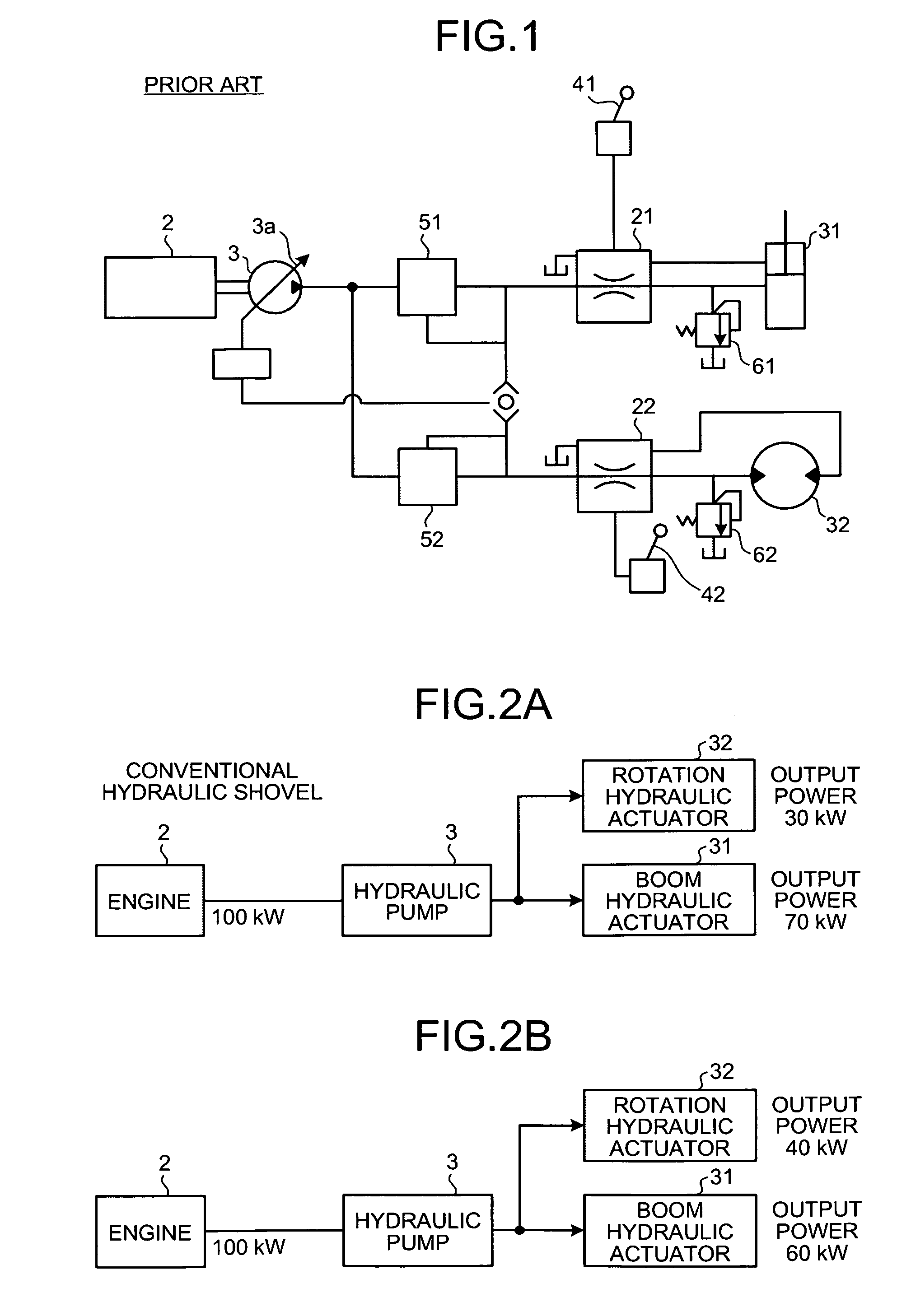
[0037]Advantages of the invention will be described below in comparison with the comparative example. As shown in FIG. 4B, when the control is performed by the first control unit, the torque generated in the rotation generator motor 11 is restricted. Therefore, the power of 15 kW is supplied to the rotation generator motor 11 from the storage device 10 while the power of 15 kW is supplied to the rotation generator motor 11 from the engine 2 which outputs the power of 100 kW, thereby supplying the total power of 30 kW to the rotation generator motor 11. The torque (100 N·m) corresponding to the current discharge pressure Pp (200 kg / cm2) of the hydraulic pump 3 or the current load pressure of the boom hydraulic cylinder 31 is generated in the rotation generator motor 11. The power of 30 kW is distributed to the rotation generator motor 11 while the power of 85 kW is distributed to the boom hydraulic actuator 31, whereby the power distribution becomes substantially equal to the ideal state (FIG. 2A). Therefore, compared with the comparative example of FIG. 4A, the rotary speed of the upper rotary body is suppressed to achieve the good speed matching between the rotation and the boom.
[0038]FIG. 4C illustrates a power distribution when the control is performed by the second control unit in addition to the control of the first control unit. As shown in FIG. 4C, when the control is performed by the second control unit, the load of the hydraulic pump 3 is further restricted. Therefore, the engine 2 outputs the power of 85 kW and the hydraulic pump 3 takes the power of 70 kW in the power of 85 kW. Similarly to FIG. 4B, as a result of the control of the first control unit, the total power of 30 kW is supplied to the rotation generator motor, 11, and the torque (100 N·m) corresponding to the current discharge pressure Pp (200 kg / cm2) of the hydraulic pump 3 or the current load pressure of the boom hydraulic cylinder 31 is generated in the rotation generator motor 11. The power of 30 kW is distributed to the rotation generator motor 11 while the power of 70 kW is distributed to the boom hydraulic actuator 31, and the power distribution becomes identical to the ideal state (FIG. 2A). Therefore, the speed matching between the rotation and the boom becomes the ideal state.
[0039]As shown in FIG. 6, unless the control is performed by the second control unit so as to restrict the load of the hydraulic pump 3, a stroke speed V′ of the boom hydraulic cylinder 31 is not gradually lowered as time of the hoist rotary work elapses (but the stroke speed V′ becomes constant or is slightly increased), and the matching between the rotary speed U of the upper rotary body and the stroke speed V′ of the boom hydraulic cylinder 31 drops slightly out from the ideal state. Because the boom lifting speed is not decreased despite the operator's intention to stop the boom lifting in a last half of the hoist rotary work, the operator feels uncomfortable feeling in the operation.
[0040]On the other hand, as shown in FIG. 5, when the control is performed by the second control unit so as to restrict the load of the hydraulic pump 3, the stroke speed V of the boom hydraulic cylinder 31 is gradually lowered as time of the hoist rotary work elapses because the pump load is restricted as described above, and the matching between the rotary speed U of the upper rotary body and the stroke speed V of the boom hydraulic cylinder 31 becomes the ideal state. Because the boom lifting speed is decreased in line with the operator's intention to stop the boom lifting in the last half of the hoist rotary work, and the operator does not feel the uncomfortable feeling in the operation.
[0041]When the control is performed by the first control unit, as can be seen from the letter A in FIG. 7B and the letter A′ in FIG. 7A, the rotary speed U of the upper rotary body is suppressed in comparison with the speed U′ of the comparative example. When the control is performed by the second control unit, as can be seen from the letter B in FIG. 7B and the letter B′ in FIG. 7A, the boom hydraulic cylinder stroke speed V is gradually decreased as the work makes the transition to the last half in comparison with the speed V′ of the comparative example. Thus, according to the invention, the speed matching between the upper rotary body and the boom can be achieved to accurately perform the hoist rotary work with good operability.

Problems solved by technology

The pressure compensation valves 51 and 52 make the supply of the pressurized oil difficult by reducing the pressurized oil supplied to the control valve on the side on which the smaller load is applied.
However, when the hoist rotary work is performed in the configuration, the following problems are generated.
Therefore, the excessive pressurized oil is discharged to a tank, which leads to energy loss or fuel inefficiency.

Method used


Image

  • Control apparatus for work machine
  • Control apparatus for work machine
  • Control apparatus for work machine

Examples


Embodiment Construction

[0077]Embodiments of the invention will be described below with reference to the drawings. FIG. 3 shows an overall configuration of a construction machine 1 according to an embodiment of the invention. The construction machine 1 is intended to be a hydraulic shovel.

[0078]The construction machine 1 includes an upper rotary body and a lower crawler carrier, and the lower crawler carrier includes right and left crawler tracks. A work machine including a boom, an arm, and a bucket is attached to a machine body. The boom is actuated by driving a boom hydraulic cylinder 31, the arm is actuated by driving an arm hydraulic cylinder 33 (hereinafter, sometimes referred to as “an arm hydraulic actuator 33”), and the bucket is actuated by driving a bucket hydraulic cylinder 34 (hereinafter, sometimes referred to as “a bucket hydraulic actuator 34”). The left crawler track and the right crawler track are rotated by driving a left-crawler hydraulic motor 35 and a right-crawler hydraulic motor 36 ...


PUM


Abstract

A speed of a hydraulic actuator is matched with that of an electric actuator when the hydraulic actuator and the electric actuator are concurrently actuated. When determination units (71, 72) determine that a boom hydraulic cylinder (31) and a rotation generator motor (11) are concurrently actuated based on a controlled variable of a boom control lever (41) and a controlled variable of a rotation control lever (42), a torque of the rotation generator motor (11) is restricted based on a pump discharge pressure (Pp). Therefore, for example, a torque limit command is generated and output such that a torque limit value (TL2) of the rotation generator motor (11) is decreased with a decrease in discharge pressure (Pp) of a hydraulic pump (3).

Description

TECHNICAL FIELD[0001]The present invention relates to a control apparatus for a work machine, particularly to an apparatus suitable for control of a hybrid construction machine in which a generator motor assists a driving force of an engine.BACKGROUND ART[0002]Hoist rotary work can be cited as a typical work performed by a hydraulic shovel. In the hoist rotary work, earth and sand located below are loaded by a boom, an upper rotary body is rotated by a predetermined angle (for example, 90°) while the boom is being lifted, and the earth and sand are loaded on a loading platform of a dumper truck. During the hoist rotary work, the lifting of the boom and the rotation of the upper rotary body are simultaneously performed by a combined operation of a boom control lever and a rotary control lever.[0003]A configuration of a conventional construction machine 1 will schematically be described with reference to FIG. 1. For the purpose of easy understanding, only the configuration used to act...

Claims


Application Information

Patent Timeline
Patent Type & Authority Patents(United States)
IPC IPC(8): F16D31/02
CPCB66C1/42B66F7/04E02F9/2037E02F9/2075
Inventor MORINAGA, JUNKAWAGUCHI, TADASHIINOUE, HIROAKI
Owner KOMATSU LTD
Why Eureka
Try Eureka