Film deposition apparatus
a film deposition and film technology, applied in the direction of chemical vapor deposition coating, vacuum evaporation coating, coating, etc., to achieve the effect of preferable uniformity of film thickness
- Summary
- Abstract
- Description
- Claims
- Application Information
AI Technical Summary
Benefits of technology
Problems solved by technology
Method used
Image
Examples
first embodiment
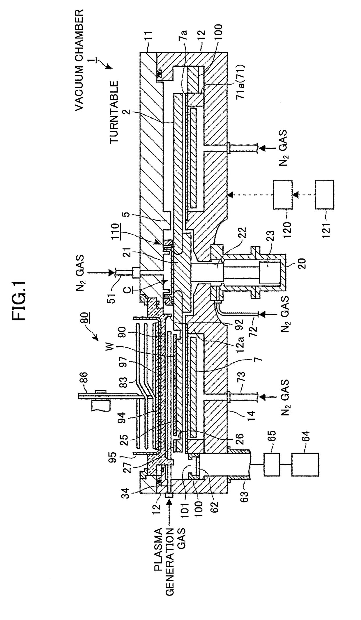
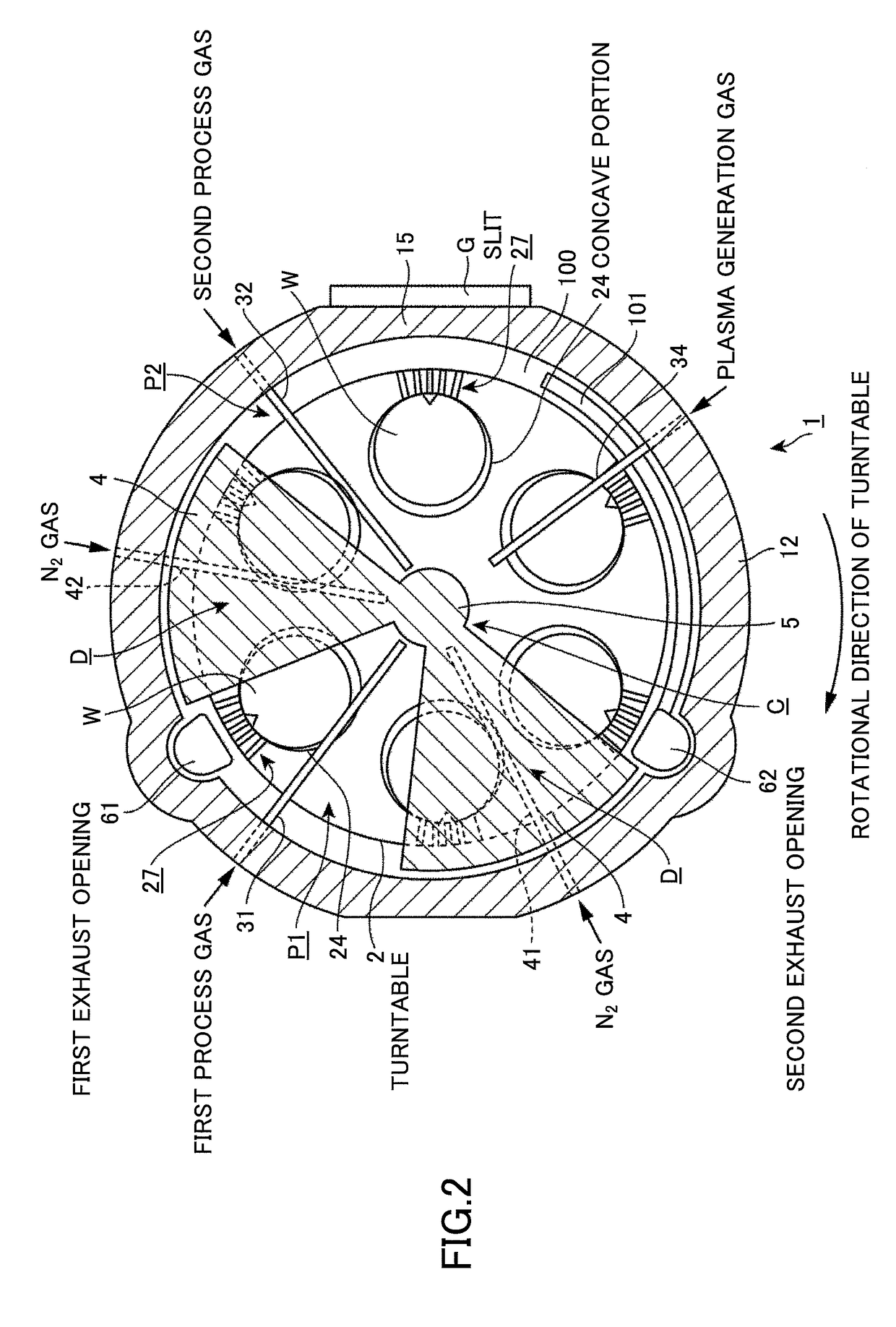
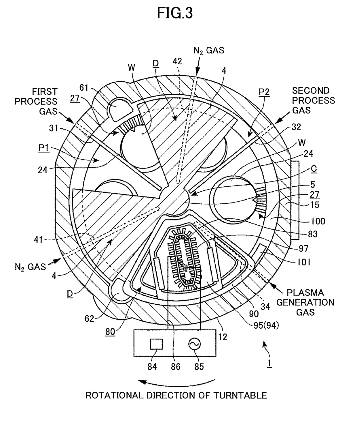
[0043]A description is given below of a film deposition apparatus according to a first embodiment of the present invention. As illustrated in FIGS. 1 through 4, the film deposition apparatus includes a flattened vacuum chamber 1 having an approximately round planar shape, and a turntable 2 provided in the vacuum chamber 1 and having its rotational center coincided with the center of the vacuum chamber 1. The turntable 2 is, for example, made of quartz. The film deposition apparatus is configured to perform a film deposition process on a wafer W.
[0044]The vacuum chamber 1 includes a ceiling plate 11 and a chamber body 12. The ceiling plate 11 is configured to be attachable to or detachable from the chamber body 12. A separation gas supply pipe 51 is connected to a central part of the upper surface of the ceiling plate 11 to supply nitrogen (N2) gas as a separation gas in order to prevent different process gases from mixing with each other in a central area C within the vacuum chamber...
second embodiment
[0079]Next, a description is given below of another embodiment of the present invention with reference to FIGS. 16 and 17. The embodiment differs from the first embodiment in that a communication passage constituted of a cut-out portion 28 having a broader width than that of the first embodiment is formed in the end area of the concave portion 24 opposite to the center O1 of the turntable 2 when seen from the center O2 of the concave portion 24 of the turntable 2 instead of the plurality of narrow slits 271 through 275. The cut-out portion 28 is formed in the wall portion of the concave portion 24 so that the groove portion 26 of the concave portion 24 is in communication with a space on the upper surface side and on the lateral side of the periphery of the turntable 2. The other configuration is similar to that of the above-discussed first embodiment. In this configuration, because the gas approaching the outer circumferential side of the turntable 2 in the concave portion 24 is al...
third embodiment
[0082]Subsequently, a description is given below of another embodiment of the present invention with reference to FIG. 21. This embodiment differs from the first embodiment in that a communication passage 29 is formed in the bottom portion of the concave portion 24 instead of providing the communication passage 29 in the side wall portion of the concave portion 24. This communication passage 29 is formed in a bottom portion 261 of the groove portion 26 of the concave portion 24 in the end area of the concave portion 24 opposite to the center O1 of the turntable 2 when seen from the center of the concave portion 24 of the turntable 2. The communication passage 29 is formed so that the groove portion 26 is in communication with a space under the turntable 2 in the vicinity of the periphery of the turntable 2. The configuration of the third embodiment is similar to that of the first embodiment except that the communication passage 29 is provided in the bottom portion 261 of the concave...
PUM
| Property | Measurement | Unit |
|---|---|---|
| angle | aaaaa | aaaaa |
| diameter | aaaaa | aaaaa |
| diameter | aaaaa | aaaaa |
Abstract
Description
Claims
Application Information
 - R&D
- Intellectual Property
- Life Sciences
- Materials
- Tech Scout
- Unparalleled Data Quality
- Higher Quality Content
- 60% Fewer Hallucinations
Browse by: Latest US Patents, China's latest patents, Technical Efficacy Thesaurus, Application Domain, Technology Topic, Popular Technical Reports.
© 2025 PatSnap. All rights reserved.Legal|Privacy policy|Modern Slavery Act Transparency Statement|Sitemap|About US| Contact US: help@patsnap.com


