Film deposition apparatus

a film deposition and film technology, applied in the direction of chemical vapor deposition coating, vacuum evaporation coating, coating, etc., to achieve the effect of preferable uniformity of film thickness

Active Publication Date: 2015-12-03
TOKYO ELECTRON LTD
View PDF7 Cites 6 Cited by
  • Summary
  • Abstract
  • Description
  • Claims
  • Application Information

AI Technical Summary

Benefits of technology

[0009]More specifically, the embodiments of the present invention may provide a film deposition apparatus that can ensure preferable uniformity of a film thickness across a substrate when depositing a film on the substrate placed on a turntable by rotating the turntable in a vacuum chamber.

Problems solved by technology

In this manner, because the wafer moves while returning to a flat state from a warped state, the wafer moves while rubbing the bottom surface of the concave portion with its peripheral part, which is liable to cause particles.

Method used


Image

  • Film deposition apparatus
  • Film deposition apparatus
  • Film deposition apparatus

Examples


first embodiment

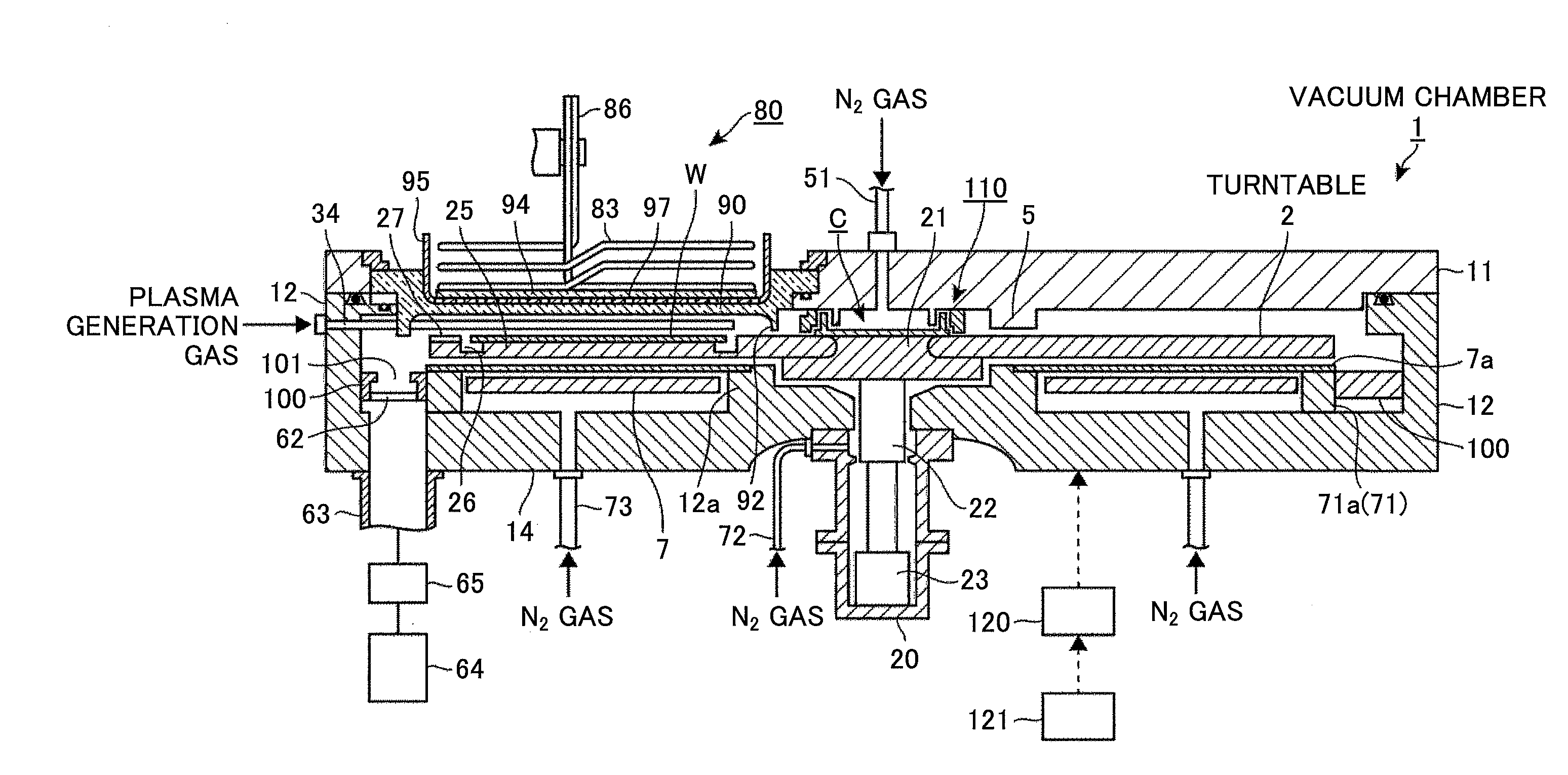
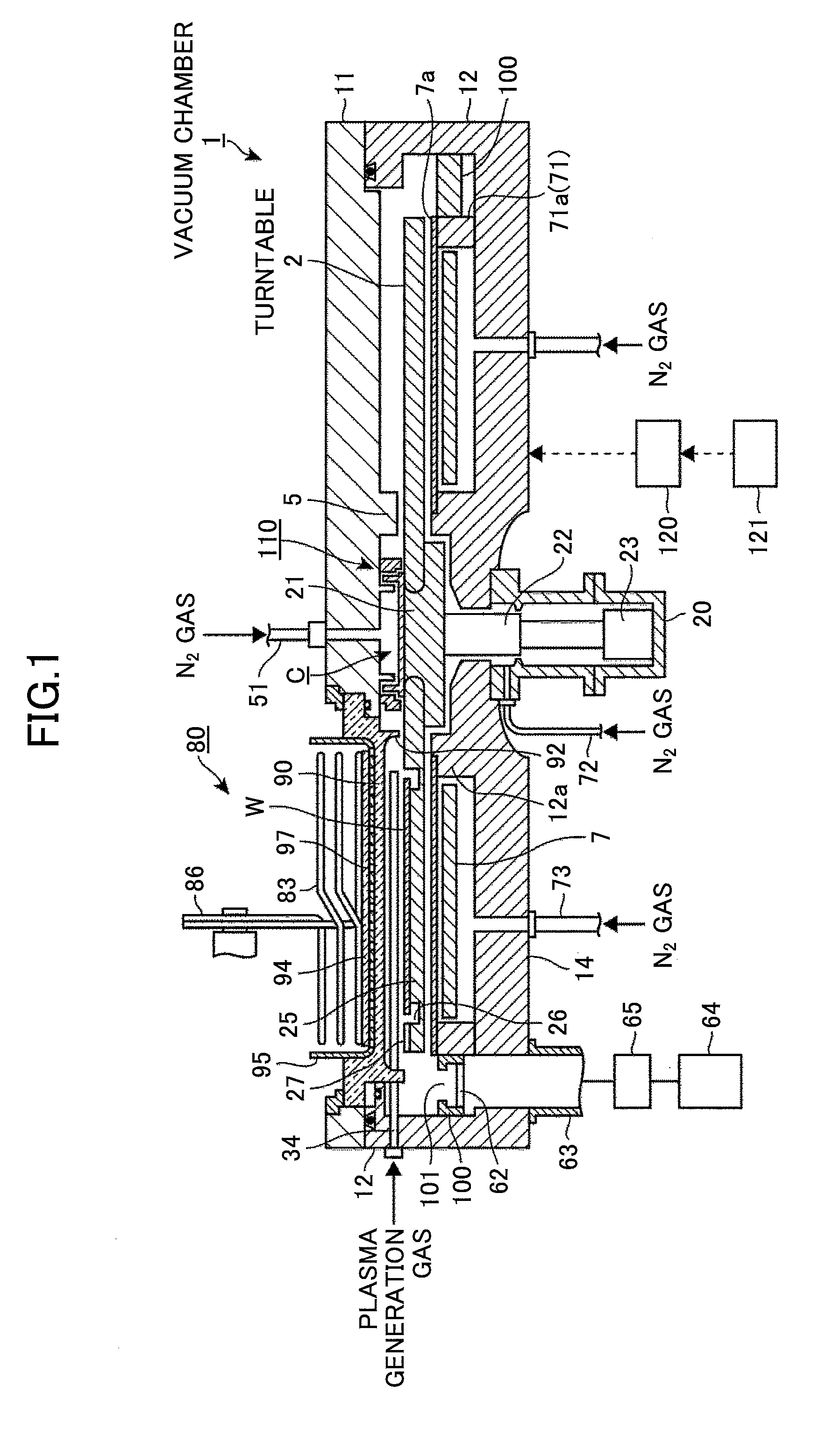
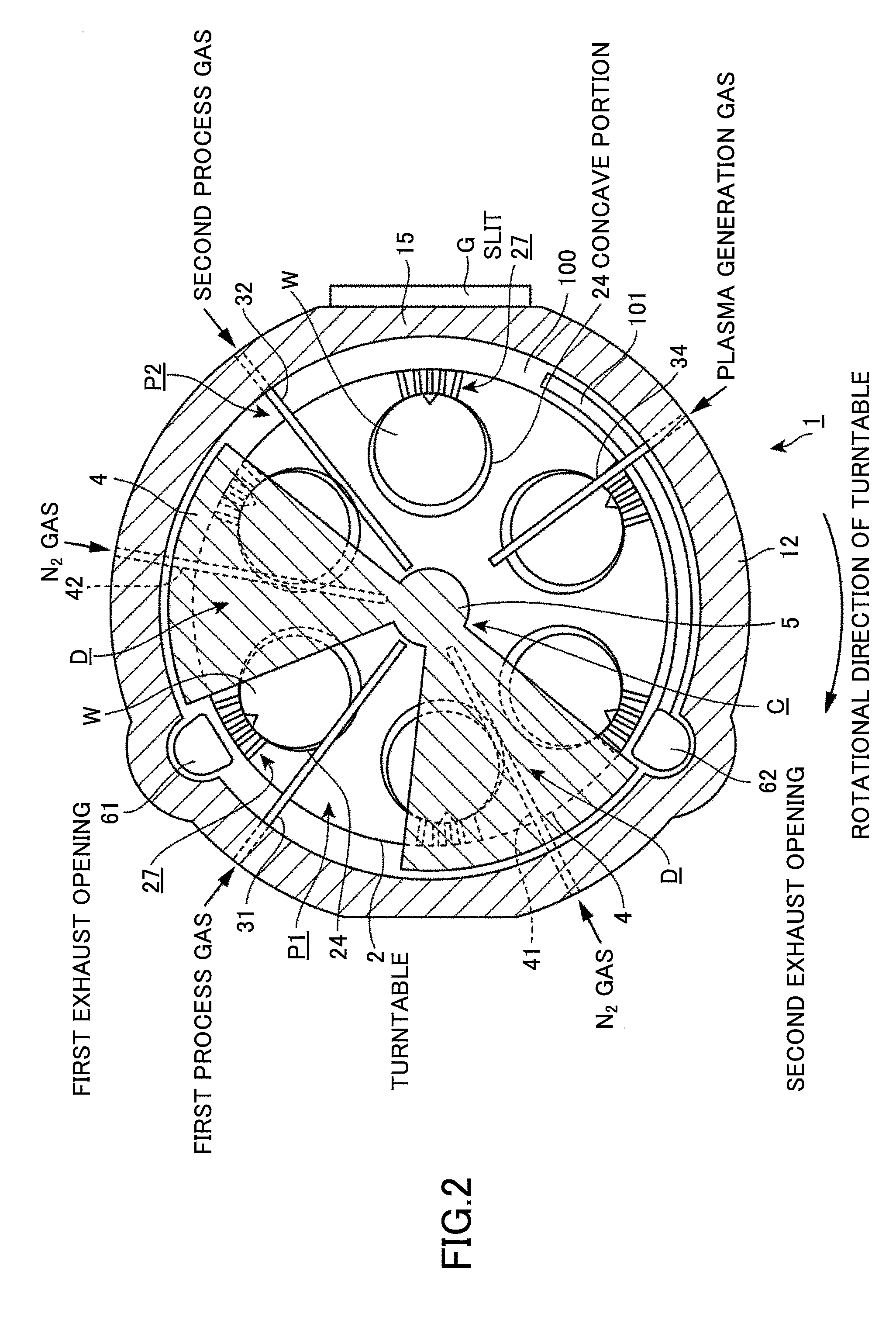
[0043]A description is given below of a film deposition apparatus according to a first embodiment of the present invention. As illustrated in FIGS. 1 through 4, the film deposition apparatus includes a flattened vacuum chamber 1 having an approximately round planar shape, and a turntable 2 provided in the vacuum chamber 1 and having its rotational center coincided with the center of the vacuum chamber 1. The turntable 2 is, for example, made of quartz. The film deposition apparatus is configured to perform a film deposition process on a wafer W.

[0044]The vacuum chamber 1 includes a ceiling plate 11 and a chamber body 12. The ceiling plate 11 is configured to be attachable to or detachable from the chamber body 12. A separation gas supply pipe 51 is connected to a central part of the upper surface of the ceiling plate 11 to supply nitrogen (N2) gas as a separation gas in order to prevent different process gases from mixing with each other in a central area C within the vacuum chamber...

second embodiment

[0080]Next, a description is given below of another embodiment of the present invention with reference to FIGS. 16 and 17. The embodiment differs from the first embodiment in that a communication passage constituted of a cut-out portion 28 having a broader width than that of the first embodiment is formed in the end area of the concave portion 24 opposite to the center O1 of the turntable 2 when seen from the center O2 of the concave portion 24 of the turntable 2 instead of the plurality of narrow slits 271 through 275. The cut-out portion 28 is formed in the wall portion of the concave portion 24 so that the groove portion 26 of the concave portion 24 is in communication with a space on the upper surface side and on the lateral side of the periphery of the turntable 2. The other configuration is similar to that of the above-discussed first embodiment. In this configuration, because the gas approaching the outer circumferential side of the turntable 2 in the concave portion 24 is al...

third embodiment

[0083]Subsequently, a description is given below of another embodiment of the present invention with reference to FIG. 21. This embodiment differs from the first embodiment in that a communication passage 29 is formed in the bottom portion of the concave portion 24 instead of providing the communication passage 29 in the side wall portion of the concave portion 24. This communication passage 29 is formed in a bottom portion 261 of the groove portion 26 of the concave portion 24 in the end area of the concave portion 24 opposite to the center O1 of the turntable 2 when seen from the center of the concave portion 24 of the turntable 2. The communication passage 29 is formed so that the groove portion 26 is in communication with a space under the turntable 2 in the vicinity of the periphery of the turntable 2. The configuration of the third embodiment is similar to that of the first embodiment except that the communication passage 29 is provided in the bottom portion 261 of the concave...


PUM

PropertyMeasurementUnit
angleaaaaaaaaaa
diameteraaaaaaaaaa
diameteraaaaaaaaaa

Abstract

A film deposition apparatus includes a vacuum chamber and a turntable provided in the vacuum chamber. A concave portion is formed in a surface of the turntable to accommodate a substrate therein, and a pedestal portion is provided to support a location inside a periphery of the substrate in the concave portion. At least one communication passage is formed in a wall portion of the concave portion to cause a first space around the pedestal portion in the concave portion to be in communication with a second space outside the turntable provided in an end area of the concave portion located opposite to a first center of the turntable when seen from a second center of the concave portion. An exhaust opening is provided to evacuate the vacuum chamber.

Description

CROSS-REFERENCE TO RELATED APPLICATIONS[0001]This patent application is based upon and claims the benefit of priority of Japanese Patent Application No. 2014-113029, filed on May 30, 2014, the entire contents of which are incorporated herein by reference.BACKGROUND OF THE INVENTION[0002]1. Field of the Invention[0003]The present invention relates to a film deposition apparatus for depositing a film on a substrate by causing the substrate on a turntable to alternately pass through a source gas supply area for supplying a source gas and a reaction gas supply area for supplying a reaction gas reactable with the source gas by rotating the turntable in a vacuum chamber.[0004]2. Description of the Related Art[0005]So-called ALD (Atomic Layer Deposition) is known as a method for depositing a thin film such as a silicon oxide (SiO2) film on a substrate such as a semiconductor wafer (which is hereinafter called a “wafer”). Japanese Laid-Open Patent Application Publication No. 2013-222948 dis...

Claims


Application Information

Patent Timeline
Patent Type & Authority Applications(United States)
IPC IPC(8): C23C16/44C23C16/458C23C16/455
CPCC23C16/4412C23C16/4584C23C16/455C23C14/50C23C16/45548C23C16/458C23C16/4583C23C16/505H01L21/02274H01L21/68764H01L21/68771
Inventor CHIBA, TAKASHIUMEHARA, TAKAHITOHASEGAWA, MASAYUKI
Owner TOKYO ELECTRON LTD
Why Eureka
Try Eureka