Method for infusing stem cells

a stem cell and infusion method technology, applied in the field of infusion systems, can solve the problems of affecting the infusion procedure, being particularly troublesome, susceptible to kinking and/or collapse, etc., and achieve the effect of preventing collaps

Active Publication Date: 2018-12-18
COOK REGENTEC
View PDF87 Cites 3 Cited by
  • Summary
  • Abstract
  • Description
  • Claims
  • Application Information

AI Technical Summary

Benefits of technology

[0015]Within the context of the present invention, several structural variations are envisioned that will facilitate the infusion of biologics into the vasculature of a patient. These variations can also enhance the diffusion and retention rate of the stem cells, drugs, proteins, or particles by the heart. These include: 1) the creation of a recollection chamber at the distal end of the catheter for establishing a safe and effective fluid infusion velocity for the biologics; 2) the orientation of the proximal (upstream) surface of a separator that will promote separation of biologics from each other prior to their infusion; and 3) an inflatable balloon that will coordinate and control blood flow through the vasculature in cooperation with the infusion of biologics. One additional variation is the use of a venous catheter in place of the catheter disclosed previously.
[0018]In combination, the separator and the recollection chamber function to promote and maintain the separation of biologics as they are being safely infused. In particular, the recollection chamber slows the fluid velocity rate of the infusion fluid, after it has been accelerated through the separator. To further maintain safe fluid flow through the vasculature, an inflatable balloon can be attached to the outer surface of the catheter and it can be selectively inflated to coordinate the respective rates of blood flow and fluid infusion.
[0019]In another aspect of the present invention, a reinforcing member is employed to strengthen the catheter wall under the inflatable balloon. With this arrangement, the catheter does not kink or collapse due to the pressure exerted on the catheter wall when the balloon is inflated. Instead, a substantially constant cross-section for the central lumen is maintained during an inflation of the balloon, allowing for the unimpeded flow of particles to pass through the central lumen during an infusion of particles into a patient's vasculature.
[0021]In one embodiment, the reinforcement member comprises an annular shaped ring that is affixed to the outer surface of the catheter wall under the inflatable balloon. With the annular shaped ring affixed, the ring is oriented substantially perpendicular to a longitudinal axis defined by the infusion catheter and concentric with the axis, to strengthen the catheter wall.
[0022]In another embodiment, a separator (as described above) acts as both a filter and the reinforcement member. For this embodiment, the separator is located under the inflatable balloon and positioned in contact with the inner surface of the wall. Thus, the separator provides the dual function of preventing particles from flocculating as they are infused into the vasculature and functions to strengthen the catheter wall to prevent collapse during balloon inflation.

Problems solved by technology

Because of the flexible nature of the catheter tube, it is typically susceptible to kinking and / or collapse during inflation of the balloon.
This can be particularly troublesome for infusion catheters where the material to be infused is pumped through a central lumen of the catheter tube.
In this instance, a collapse or even partial blocking of the central lumen where the balloon is inflated can impede fluid flow in the central lumen, and adversely affect an infusion procedure.
In addition, as described above, the use of an inflation balloon can in some cases, affect the size and geometry of the internal passages in the catheter, which in turn, can affect the levels of shear stress that are developed.

Method used


Image

  • Method for infusing stem cells
  • Method for infusing stem cells
  • Method for infusing stem cells

Examples


Embodiment Construction

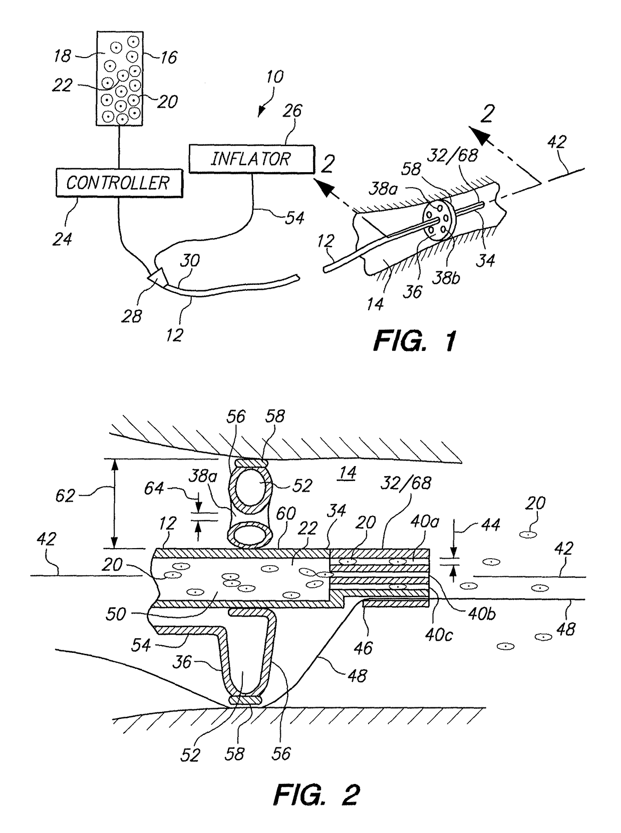
[0041]Referring initially to FIG. 1 a system for introducing (infusing) a fluid in accordance with the present invention is shown and is generally designated 10. As shown, the system 10 includes a catheter 12 that can be advanced into a vessel 14 to position the catheter 10 at a predetermined location in the vasculature of a patient (not shown). For the purposes of the present invention, the vessel 14 is preferably an artery or a vein in the cardiovascular system of a patient, and the system 10 is used for an intra-arterial, intravenous or intracoronary protocol.

[0042]In detail, FIG. 1 shows that the system 10 includes a source 16 for holding a fluid medium 18. As also shown in FIG. 1, a plurality of particles 20 are suspended in the fluid medium 18 to create a particle / fluid medium 22. For the present invention, the particles 20 may be some form of a drug or, most likely, they will be some form of a biologics (i.e. cell, gene or protein). In any event, the particles 20 will be susp...


PUM

PropertyMeasurementUnit
angleaaaaaaaaaa
forceaaaaaaaaaa
lengthaaaaaaaaaa

Abstract

A method for infusing a liquid into a patient's vasculature in accordance with an infusion protocol is disclosed. For this method, an infusion catheter having a multi-lumen infusion unit that is mounted adjacent the catheter's distal end is positioned in an artery within a predetermined distance from an intended target tissue surface. An inflation balloon is then deployed to at least partially occlude the artery and a force is exerted on the liquid to establish a flow rate for the liquid in the catheter. Specifically, the force is exerted to infuse the liquid from the catheter through the infusion unit and into the vasculature with a homogeneous distribution of the liquid to cover the intended surface of the target tissue. The flow rate can be established in accordance with an infusion protocol that is characterized by time and liquid volume parameters based on viscosity and pressure values in the liquid.

Description

REFERENCE TO RELATED APPLICATIONS[0001]This application is a continuation-in-part of application Ser. No. 14 / 145,158 filed Dec. 31, 2013 which is currently pending, and which is a continuation-in-part of application Ser. No. 13 / 473,988 filed May 17, 2012, which issued as U.S. Pat. No. 8,790,298 on Jul. 29, 2014 and which is a continuation-in-part of application Ser. No. 12 / 563,876, filed Sep. 21, 2009, which issued as U.S. Pat. No. 8,647,311 on Feb. 11, 2014. The contents of application Ser. No. 14 / 145,158, application Ser. No. 13 / 473,988 and U.S. Pat. No. 8,647,311 are each incorporated by reference herein.FIELD OF THE INVENTION[0002]The present invention pertains generally to infusion systems for introducing particles into a fluid stream. More particularly, the present invention pertains to infusion systems for introducing (infusing) particles of biological matter (e.g. stem cells) into the vasculature of a patient without diminishing the therapeutic effectiveness of the biologica...

Claims


Application Information

Patent Timeline
Patent Type & Authority Patents(United States)
IPC IPC(8): A61M5/168A61M25/00A61L29/16A61M25/10A61M39/10A61M39/08A61M25/01A61M5/14
CPCA61M25/0023A61L29/16A61M25/0071A61M25/0075A61L2300/64A61L2400/06A61M2206/18A61M39/105A61M2005/1404A61M2025/0183A61M2025/1097A61M2039/085A61M2205/3334A61M25/1002
Inventor DIB, NABILKOHLER, ROBERT EDWARD
Owner COOK REGENTEC
Why Eureka
Try Eureka