Supercharge Your Innovation With Domain-Expert AI Agents!

Method for manufacturing valve unit, and valve unit

a manufacturing method and valve body technology, applied in the direction of valve operating means/release devices, diaphragm valves, engine diaphragms, etc., can solve the problems of difficult to generate wrinkles, the film is not uniform, and the valve body cannot be properly operated, so as to reduce the dimension of the valve unit and high accuracy

Active Publication Date: 2018-12-18
SEIKO EPSON CORP
View PDF23 Cites 1 Cited by
  • Summary
  • Abstract
  • Description
  • Claims
  • Application Information

AI Technical Summary

Benefits of technology

This patent describes a method for covering flow channels with a flexible material in a way that ensures accurate positioning of the flexible material and prevents abnormalities such as wrinkles. This method also helps in aligning the flow channels with high accuracy when a positioning pin is used. The technical effects of this invention include improved accuracy and reliability of the valve unit and reduced dimensions of the valve unit.

Problems solved by technology

For example, when there are abnormalities such as wrinkles in the film, a variation in the rigidity of the film surface occurs, and displacement of the film becomes non-uniform.
When the film is sealed with applied tension, it is difficult for wrinkles to be generated.
However, in JP-A-2013-124713, since positioning of the film is performed by only applying tension to the film, there is a concern that the film will be sealed in a manner in which the position of the film with respect to the valve body and the position of a pressure receiving plate with respect to the valve body are shifted, and as a result proper operation of the valve body will not be possible.
Accordingly, it is difficult for a positional shift of the flexible member to occur.
In covering the first flow channel member with the flexible member, it is difficult for the pressure receiving plate, which is supported by the fixing member, to move.
Therefore, it is also difficult for the flexible member, to which the pressure receiving plate is fixed, to move.
Accordingly, in covering the first flow channel member with the flexible member, it is difficult for a positional shift of both the pressure receiving plate and the flexible member to occur.
Therefore, it is difficult for wrinkles to be generated in the flexible member in covering the first flow channel member with the flexible member.
When the flexible member is displaced as a result of suction from a side of the one surface, it is difficult for unnecessary heating of the displaced portions to have an effect on the flexible member.

Method used


Image

  • Method for manufacturing valve unit, and valve unit
  • Method for manufacturing valve unit, and valve unit
  • Method for manufacturing valve unit, and valve unit

Examples


embodiment 1

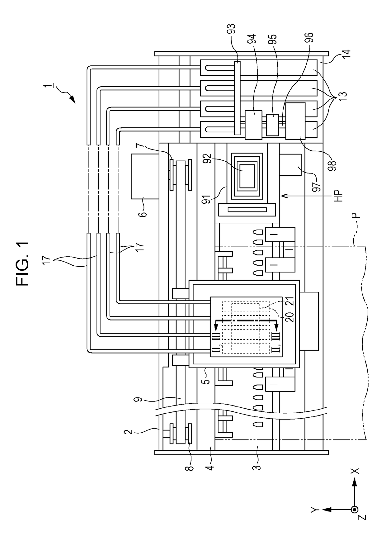
[0043]FIG. 1 is a schematic plan view that shows a configuration of an ink jet type recording apparatus (hereinafter, referred to as a printer) according to Embodiment 1. A printer 1 is an apparatus that performs recording or printing of an image, or the like, on a recording medium P, such as recording paper, by ejecting an ink in liquid form onto a surface of the recording medium P.

[0044]As shown in FIG. 1, the printer 1 includes a main body case 2 having a substantially rectangular box form, and a platen 3 installed in a front lower section inside the main body case 2 in a longitudinal direction (the left-right direction in FIG. 1) of the main body case 2, which corresponds to a main scanning direction. The platen 3 is a support platform having a substantially rectangular shape and that supports a recording medium P, such as sheets of recording paper. A recording medium P is transported on the platen 3 in a sub-scanning direction (a forward direction), which is orthogonal to the m...

embodiment 2

[0147]FIG. 6 is a diagram that describes a manner of a method for manufacturing a valve unit according to Embodiment 2. To explain in more detail, FIG. 6 is a diagram that corresponds to FIG. 5A, and describes a step (Step S1) of adhering the first flow channel member 45 and the film 22.

[0148]In the method for manufacturing the valve unit 21 according to the present embodiment, in Step S1, the manners of the heating tool and the pressing force member are different from those of Embodiment 1, but the rest is the same as Embodiment 1.

[0149]Hereinafter, the method for manufacturing the valve unit 21 according to the present embodiment will be described with reference to FIG. 6 focusing on the points that differ from Embodiment 1. In addition, structures that are the same as those of Embodiment 1 will be given the same reference numerals, and overlapping descriptions thereof will be omitted.

[0150]In Step S1, as shown in FIG. 6, the film 22 is fixed or caused to adhere to the first flow ...

embodiment 3

[0159]FIG. 7 is a diagram that describes a manner of a method for manufacturing a valve unit according to Embodiment 3. To explain in more detail, FIG. 7 is a diagram that corresponds to FIG. 5A, and describes a step (Step S1) of adhering the first flow channel member 45 and the film 22.

[0160]In the method for manufacturing the valve unit 21 according to the present embodiment, in Step S1, the method for supporting the film 22 using the inclined surface 122 of the second member 120 is different from that of Embodiment 1, but the rest is the same as Embodiment 1.

[0161]Hereinafter, the method for manufacturing the valve unit 21 according to the present embodiment will be described with reference to FIG. 7 focusing on the points that differ from Embodiment 1. In addition, structures that are the same as those of Embodiment 1 will be given the same reference numerals, and overlapping descriptions thereof will be omitted.

[0162]In Step S1, as shown in FIG. 7, the film 22 is fixed to the f...


PUM

PropertyMeasurementUnit
flexibleaaaaaaaaaa
pressureaaaaaaaaaa
internal pressureaaaaaaaaaa

Abstract

A method for manufacturing a valve unit includes fixing a first flow channel member and a flexible member to one another, the first flow channel member including a first surface, a second surface and a through-hole passing through the first surface and the second surface, in a manner in which the flexible member is supported by a fixing member and the through-hole is covered at the first surface side thereof by the flexible member; and fixing the first flow channel member and a second flow channel member, the second flow channel member including a hole through which a valve body passes, in a manner in which the through-hole is in communication with the hole at the second surface side of the through-hole, the valve body configured to open and close a flow channel in communication with the through-hole according to displacement of the flexible member.

Description

BACKGROUND1. Technical Field[0001]The present invention relates to a method for manufacturing a valve unit that supplies a liquid (an ink) to a liquid droplet ejecting head (a recording head) from a liquid supply source, and to a valve unit manufactured using the corresponding manufacturing method.2. Related Art[0002]In the related art, there is known an ink jet type recording apparatus that records or prints images on a recording medium by moving, relative to the recording medium, a liquid droplet ejecting head (a recording head) that ejects an ink as liquid droplets.[0003]For example, in the above-mentioned recording head, ink inside an ink cartridge (a liquid supply source), in which ink in liquid form is stored, is introduced into a pressure chamber through a reservoir (a common liquid chamber) of a recording head, a pressure fluctuation is applied to ink inside the pressure chamber by driving a pressure generation unit such as a piezoelectric vibration element or a heat-emittin...

Claims


Application Information

Patent Timeline
Patent Type & Authority Patents(United States)
IPC IPC(8): F16K31/00B29C65/30B41J2/175B29C65/16F16K7/17B29C65/00B29K667/00B29L31/00
CPCB41J2/17596B29C65/1635B29C65/30F16K7/17B29C66/53421B29L2031/7506B29K2623/12B29K2667/003B29C66/72325B29K2507/04B29C65/1677B29C65/18B29C65/305B29C65/7808B29C65/7814B29C65/7844B29C66/1122B29C66/474B29C66/53461B29C66/54B29C66/71B29C66/7234B29C66/73921B29C66/8322B41J2/175B41J2/17509B29K2023/12B29K2067/003
Inventor OKUI, HIROAKI
Owner SEIKO EPSON CORP
Features
  • R&D
  • Intellectual Property
  • Life Sciences
  • Materials
  • Tech Scout
  • Unparalleled Data Quality
  • Higher Quality Content
  • 60% Fewer Hallucinations
Learn More